1 - Amber | 2 - Green | 3 - Green | Interpretation |
|
|
|
|
Flashing 1 Hz | On | Off | An overtemperature condition exists. |
Flashing 2 Hz | Flashing 2 Hz | Off | The capacitor pack is not attached. |
Flashing 2 Hz | Flashing 2 Hz | On | The capacitor has been charging for 10 minutes, but |
|
|
| has not reached sufficient charge to perform a full |
|
|
| backup. |
|
|
|
|
On | On | Off | The current backup is complete, but power fluctuations |
|
|
| occurred during the backup. |
On | On | On | The cache module microcontroller has failed. |
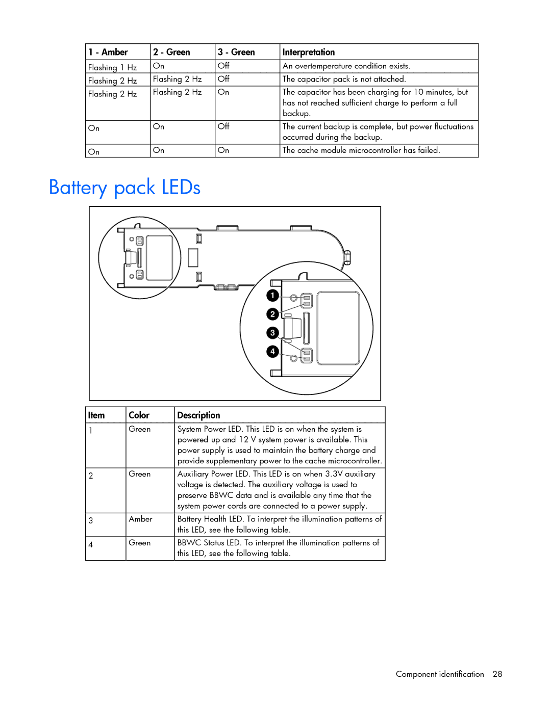
Battery pack LEDs
Item | Color | Description |
|
|
|
1 | Green | System Power LED. This LED is on when the system is |
|
| powered up and 12 V system power is available. This |
|
| power supply is used to maintain the battery charge and |
|
| provide supplementary power to the cache microcontroller. |
|
|
|
2 | Green | Auxiliary Power LED. This LED is on when 3.3V auxiliary |
|
| voltage is detected. The auxiliary voltage is used to |
|
| preserve BBWC data and is available any time that the |
|
| system power cords are connected to a power supply. |
|
|
|
3 | Amber | Battery Health LED. To interpret the illumination patterns of |
|
| this LED, see the following table. |
|
|
|
4 | Green | BBWC Status LED. To interpret the illumination patterns of |
|
| this LED, see the following table. |
|
|
|
Component identification 28