Compaq Presario V3500 and V3700 Notebook PCs
Page
Safety warning notice
Iv Safety warning notice
Table of contents
Setup Utility
Screw listing
Recycling
Product description
Intel Core Duo processors
Chipset
Intel Pentium Dual-Core processors
AMD processors
UMA nVidia
Graphics NVidia Discrete PCI Express × 16 Graphics
Mobile Intel Graphics Media Accelerator
Panel
Memory
Hard drives
Optical drives
Diskette drive
Camera
Microphone
Audio
Power
External media
Card
Ports
Security
Operating system Preinstalled
Serviceability End-user replaceable Parts
External component identification
Top components
Display components
Component Description
Options
Panel System and Maintenance Power
Button and speakers
Keys
Component Function
Lights
TouchPad
Front components
Left-side components
Rear component
Right-side components
Bottom components
Illustrated parts catalog
Serial number location
Item Description Spare part number
Inch, WXGA, BrightView display assembly
Computer major components
Keyboards
Speaker assembly
ExpressCard assembly
Description Spare part number
TouchPad
463975-001
Batteries
Power connector cable
Fan/heat sink mounting bracket not illustrated
Wlan modules
Item Description Spare part number
Illustrated parts catalog
Display bezels
Display assembly components
Optical drives include bezel
Wireless Antenna Kit
Left and right display hinges Display switch module
Antenna, microphone cable kit not illustrated
Display Hinge Kit
Rubber display kit not illustrated
Door/Cover Kit
Item Description Spare part number Door/Cover Kit 417074-001
Cable Kit
Item Description Spare part number Cable Kit 430474-001
Mass storage devices
Mass storage devices
Miscellaneous parts
Spare part Description Number
Sequential part number listing
Screw Kit
Cable, LED board, and LED board cable
Sequential part number listing
Illustrated parts catalog
Includes display panel cable
Dimm
Connector
Illustrated parts catalog
Sequential part number listing
Illustrated parts catalog
Removal and replacement procedures
Preliminary replacement requirements
Service considerations
Tools required
Cables and connectors
Grounding guidelines
Electrostatic discharge damage
Packaging and transporting guidelines
Equipment guidelines
Material Use Voltage protection level
Unknown user password
Component replacement procedures
Serial number
Computer feet
For use in computer models with Intel processors
Battery
For use in computer models with Intel or AMD processors
Hard drive
For use in computer models with AMD processors
Page
Page
Wlan module
802.11a/b/g/n Wlan modules
802.11a/b/g Wlan modules
802.11b/g Wlan module for use in Thailand
Broadcom 802.11b/g Wlan modules
802.11n Wlan modules
Description Spare part number
Page
RTC battery
Memory module
Page
Optical drive
Page
Keyboard
For use Spare part number
Page
Page
Switch cover
Page
Display assembly
Keyboard see Keyboard on Switch cover see Switch cover on
Page
Page
Page
Page
Page
Camera module
Description Spare part number
Page
Top cover
Page
Page
TouchPad cable
Page
Wireless switch board
Page
Modem module
Connectors, infrared lens, and audio board cable
Audio board
Bluetooth module
USB board
Hard drive see Hard drive on
Speaker assembly
Description Spare part number Speaker assembly 417089-001
Page
Power connector cable
For use only in computer models with AMD processors
System board
For use only in computer models with Intel processors
Page
ExpressCard assembly
Page
Page
Fan/heat sink assembly
Page
Page
Processor
Intel Celeron M processors
Description Spare part number
Page
Changing the language of the Setup Utility
Setup Utility
Starting the Setup Utility
Displaying system information
Navigating and selecting in the Setup Utility
Restoring default settings in the Setup Utility
Using advanced Setup Utility features
Closing the Setup Utility
Setup Utility menus
Select To do this
Security menu
Primary Hard Disk Self Test
Setup Utility
Metric
Specifications
Computer specifications
Inch, WXGA, BrightView display specifications
Hard drive specifications
250-GB 160-GB 120-GB 80-GB
Access time
Transfer mode
Applicable disc Read Write
Center hole diameter
System DMA specifications
Hardware DMA System function
System interrupt specifications-Intel processors
Hardware IRQ System function
System interrupt specifications-AMD processors
System I/O address specifications-Intel processors
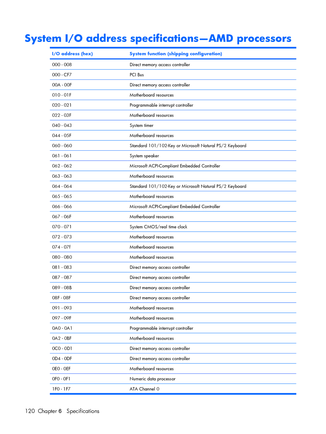
Address hex System function shipping configuration
VGA
System I/O address specifications-AMD processors
System I/O address specifications-AMD processors
System memory map specifications-Intel processors
Size Memory address System function
System memory map specifications-AMD processors
Memory address System function
FEE00000 Feefffff
Screw listing
Phillips PM2.0×5.0 captive screw
Color Quantity Length Thread Head diameter Black
Phillips PM2.5×4.0 screw
Page
Phillips PM3.0×4.0 screw
Color Quantity Length Thread Head diameter Silver
Phillips PM2.0×3.0 screw
Page
Phillips PM2.5×9.0 screw
Page
Black Phillips PM2.5×7.0 screw
Page
Black Phillips PM2.0×5.0 screw
Page
Black Phillips PM2.5×5.0 screw
Page
Silver Phillips PM2.0×2.0 screw
Black Phillips PM2.0×4.0 screw
Black Phillips PM2.0x3.0 screw
Phillips PM2.0×13.0 captive screw
Color Quantity Length Thread Head diameter Silver 13.0 mm
Backing up your information
Backup and Recovery
Recovering system information
Using system restore points
Back up suggestions
Creating recovery discs
Restore to a previous date and time
Reinstalling software programs and drivers
Reinstalling preinstalled programs and drivers
Performing a recovery
Recovering from the recovery discs
Deleting the recovery partition on the hard drive
Updating reinstalled software
Connector pin assignments
Pin Signal
Audio-out headphone
Audio-in microphone
External monitor
RJ-11 modem
RJ-45 network
Video-out
Universal Serial Bus
Power cord set requirements
Requirements for all countries or regions
Requirements for specific countries or regions
Country/region Accredited agency Applicable note number
Display
Battery
Recycling
Page
Page
Page
Page
Page
Symbols/Numerics
Index
150 Headset, spare part number Index
Hinge
116 117 External media cards Memory map 122 123 Graphics