V3715LA, V3715TU, V3763TU, V3751TU, V3752TU specifications
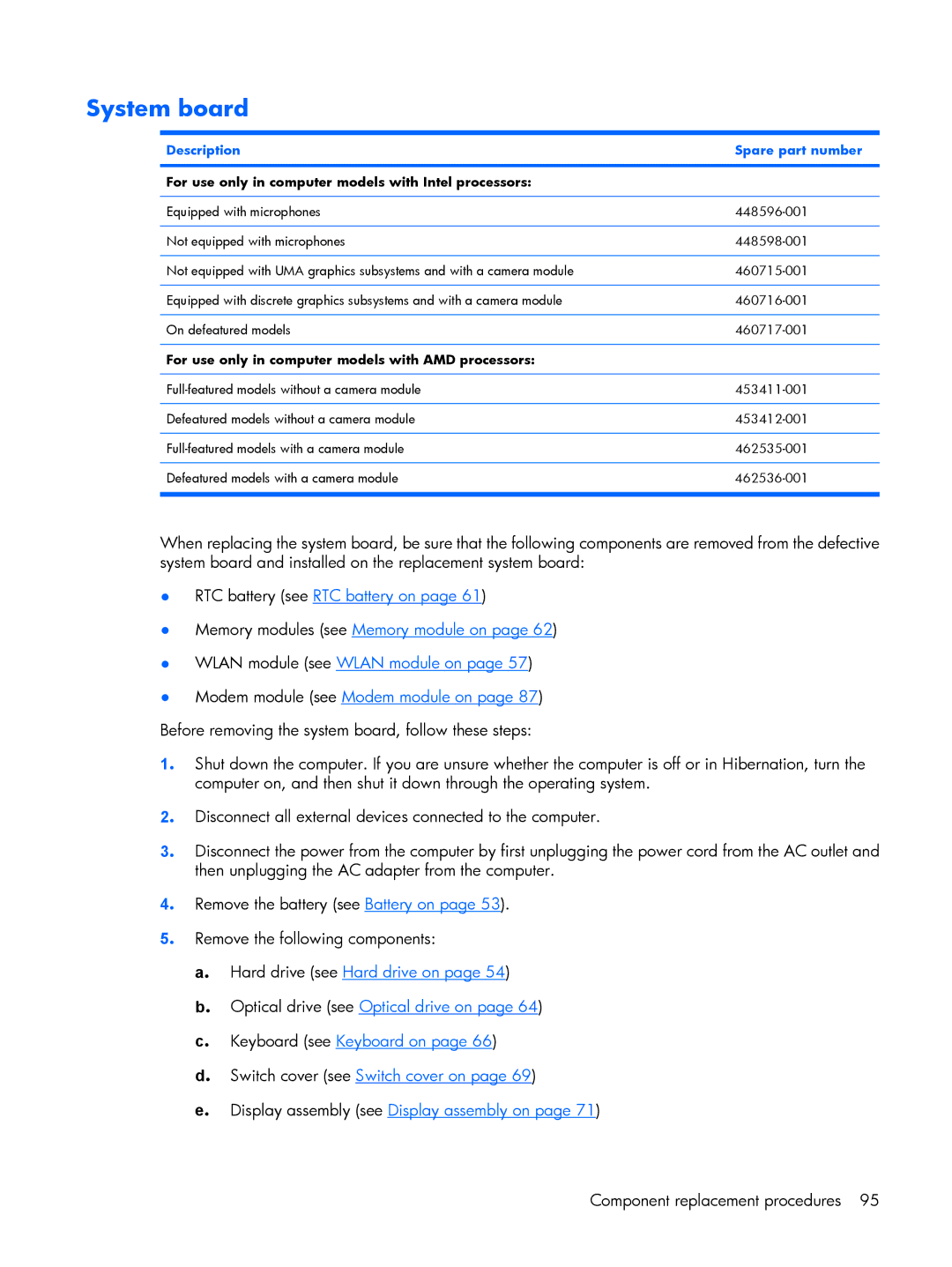
The HP V3914TU, V3814AU, V3857TU, V3801TU, and V3651AU are a series of laptops known for their balance of performance and affordability. Each model caters to different user needs, making them suitable for students, professionals, and casual users alike. These laptops often come with varying configurations, allowing users to choose according to their preferences and requirements.The HP V3914TU is powered by Intel processors, usually featuring the Intel Pentium or Core i3 series. This model typically includes 4 GB of RAM, which can be expanded depending on the user's needs, and offers a 500 GB hard drive for ample storage. The integrated Intel HD graphics make it suitable for everyday tasks such as web browsing, word processing, and light gaming. Additionally, its 15.6-inch display strikes a good balance between portability and usability, offering a resolution that supports basic multimedia consumption.
On the other hand, the V3814AU is known for its AMD A-Series processors. This model is geared towards users who prefer AMD's offering, which provides decent performance for both productivity and entertainment purposes. With similar RAM configurations as the V3914TU, the V3814AU also comes with a 15.6-inch display and typically features integrated Radeon graphics. This makes it a good option for those who need a reliable laptop for multimedia tasks and casual gaming.
The V3857TU, another model in this lineup, stands out for its robust design and enhanced cooling features. It is built to withstand daily wear and tear, making it ideal for students and professionals on the go. It continues to offer a range of Intel processors, capable of handling multitasking and productivity applications with ease.
The HP V3801TU takes a minimalist approach with its streamlined design and lightweight chassis, making it one of the most portable options in this series. Ideal for frequent travelers, it also retains the specifications found in its counterparts, ensuring that users have the power they need while maintaining mobility.
Lastly, the V3651AU serves as a budget-friendly option without sacrificing essential features. It often comes with AMD processors and offers sufficient performance for basic tasks, making it perfect for students or users who primarily use their laptops for web browsing and media consumption.
Overall, the HP V series laptops are characterized by their versatility, affordability, and reliable performance, meeting the needs of a diverse range of users. With options between Intel and AMD processors, users can make informed choices based on performance requirements and budgets.
