To use this product safely
Technical Manual Ver
Table of Contents
Table of Contents
RGB signals from AV devices other than PCs
Precautions
Introduction
Input
Features and Functions of this device
Specifications
PC signals supported
Input Response Signals
Refresh rate
Dot x Line Vertical
External Dimensions
Connection panel
Light Sensor for the remote/ambient light Sensor/indicator
Main Unit Operation Panel
Main unit
Controls and Connectors
Main unit Operation panel on the main unit
Plasma Display Section
567
Video Card PDA-5004 Section
Video Card PDA-5003 Section
INPUT2 DVI-D 24 pin connector female Pin layout
INPUT1 Mini D-sub, 15-pin connector female Pin layout
Pin layout
Combination IN/OUT terminal pin layout
Remote Control Unit
Safety Precautions
Installation Site Requirements
Power requirements
Temperature and humidity conditions
Effective remote control distance
Prevent condensation
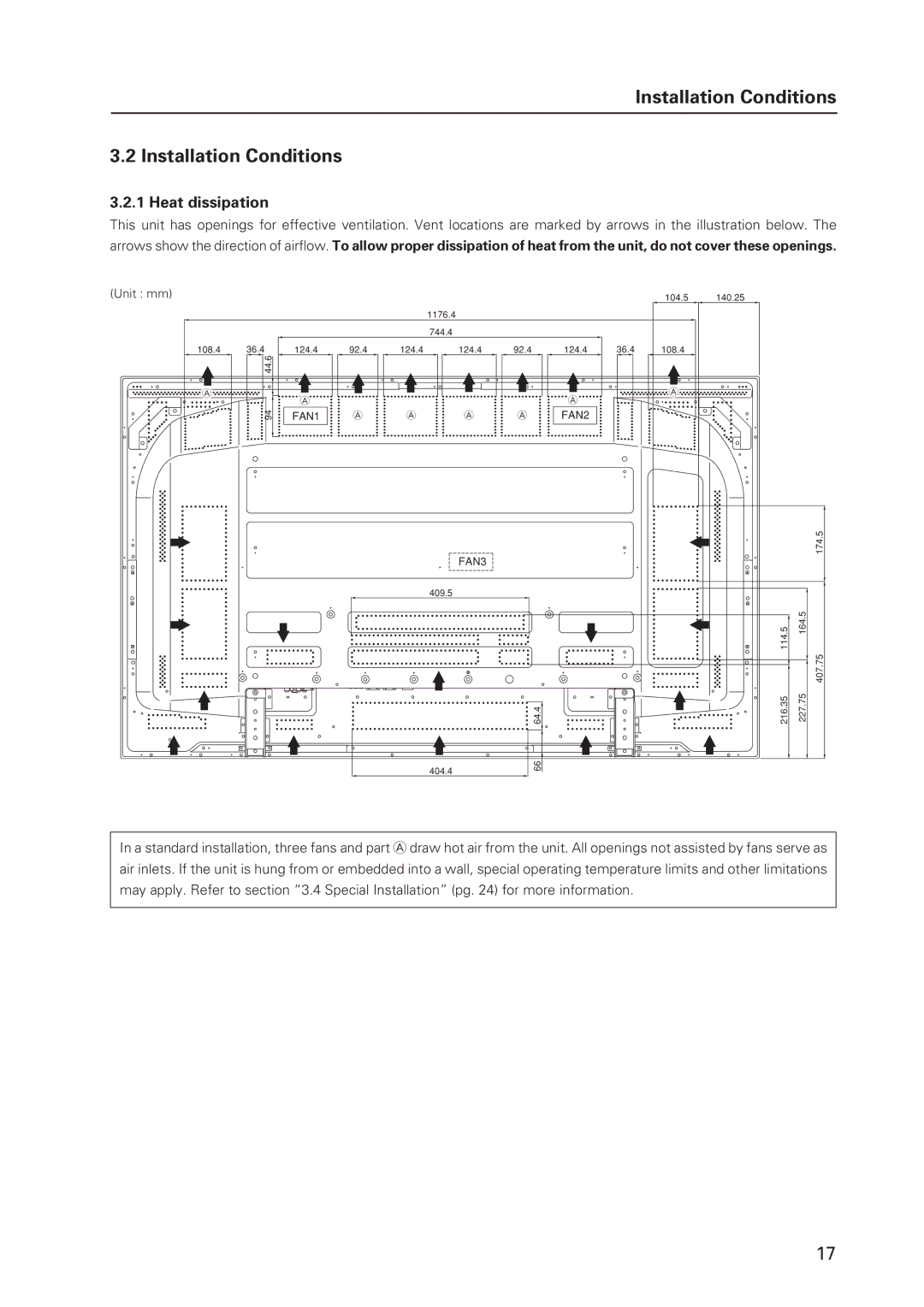
Heat dissipation
Installation Conditions
Product mounting holes
Rear view diagram Side view diagram
Calculating heat quantity
Methods of securing
Mounting surface warping
Transportation precautions
Installation Procedures
Unpacking
Ref. No Terms
Wiring
Using pliers, twist the clamp 90 and pull outward
Organize cables together using the provided speed clamps
To attach the speed clamps to the main unit
To remove speed clamps
Operating environment for standard installation
Special Installation Mounting to fittings
Ambient Temperature 0 C to 40 C examples 1
Operating environment for vertical installation *1
Vertical installation Example
Hanging on the wall
Requirements when used with PDP-S55-LR speaker system
Special Instruction Hanging on the wall
Flush-wall installation
Special Installation Hanging on the wall
Wall-mounted installation
Wall-embedded installation
Operating Temperature Restrictions
Special Installation Embedding in the wall
Embedding in the wall
Viewed from Above
Thermometer temperature measurement point
Embedding in walls with no space provided behind the unit
When the display is put in a box
Special installation When the display is put in a box
Usage temperature conditions BOX air temperature
Ambient temperature 0 C to 35 C
Ambient Temperature 0 C to 40 C
Special Installation Ceiling suspension with wires
Ceiling suspension with wires
Special Installation Ceiling suspension with wires
Hanging on the wall lengthwise
Special Installation Hanging on the wall lengthwise
Operating Temperature Restrictions *1
Installation is not possible
Viewed from Above Viewed from the Right Side
Temperature in space X and Y Mm to 370 mm
Page
Embedding in walls with no space provided behind the unit
Page
Horizontal surface Operating Temperature Restrictions *1
Special Installation Installed facing upward
Installed facing upward
Usage temperature conditions *1
Mm or more To 40 C
Special installation Horizontal connections
Horizontal connections
Mm to 300 mm or less To 35 C Mm or more To 40 C
Special installation Multiple
Multiple
¶ Video Card PDA-5003/PDA-5004
Standard Mounting Components Features and Characteristics
¶ Table Top Stand PDK-TS26
¶ Wall Mount Unit PDK-WM03
Handling the Standard Mounting Components
Handling precautions
Precautions for installation contractors
Video Card PDA-5003/PDA-5004
Specifications
PDA-5004 Video-related
Accessories
PDA-5004
External Dimensions
PDA-5003
Connection panel when equipped with PDA-5004
Connection panel when equipped with PDA-5003
Installation Notes
Installing procedures
Installation
Impedance selector switch is found only on the PDA
Holding the inside tabs, pull the video card straight out
Remove the two screws holding the video card
When using PDA-5003
Input connectors on the Plasma Display with video card
When using PDA-5004
Connection to INPUT1 and INPUT5
On-screen setup is necessary after connection
When connecting to Analog RGB in INPUT1
When connecting to Analog RGB INPUT5
When connecting to Component Video INPUT5
Connection of G on Sync analog RGB source
Connection of separate Sync analog RGB Source
Connection of composite Sync analog RGB Source
To an external monitor
When connecting to Analog RGB OUT INPUT1
INPUT1
Connection to INPUT3
Connection to INPUT2
Connection to INPUT4
Computer or AV component
About DTV set top box connection
Video Video signal
Signal type Signal format
Audio connections for component connected to
Audio connections
Audio connection for component connected to
INPUT3
Input 1
Signal Format Remark
Vertical Horizontal Signal Remark
Applies only when equipped with PDA-5003/PDA-5004
Other factors
Package dimensions
Table Top Stand PDK-TS26
External Dimensions When using Plasma Display
Stand assembling
Attaching the Stand to the Plasma Display
Attachment Restrictions
Wall Mount Unit PDK-WM03
Components
Center of the display
Attaching the metal fittings
Hardware assembly and Plasma Display attachment
Installing the hung on wall unit on the wall
Installing the Plasma Display
Speaker System PDP-S55-LR
External Dimensions when mounted to the Plasma Display
Install the speaker system according to the steps 1 through
Installation on the Plasma Display
Installation procedure
Speaker System PDP-S55-LR
Care and Maintenance When the cabinet gets dirty
Speaker System PDP-S55-LR
Operation Mode
Before Beginning Adjustment
Before Beginning Adjustments
Input correspondence signals personal computer signals
List of Input Correspondence Signals
Resolution Refresh rate
Not available
Screen size
Screen size Personal computer signal
DOT by DOT
Full
INPUT1, INPUT5
Screen size Signal Format
Signal Format Screen size Remark
640x480 59.9 Hz 31.5 kHz
INPUT2
Refresh rate Screen size Dot x line
When a video card is installed Personal computer Screen size
Menu Mode PDP-607CMX
List of Adjustable and Settable Items
Before Beginning Adjustments
PDA-5003/PDA-5004
Slot card other than PDA-5003/PDA-5004
Integrator mode PDP-607CMX
Applicable only when a PDA-5003/PDA-5004 is installed
PDA-5003/PDA-5004
Slot card other than PDA-5003/PDA-5004
Saving to Memory
Last Memory
Aging
149 351
Normal Operating Mode Normal Operation Mode
About normal operation mode
Lower right Upper right Lower left
Normal Operating Mode
Side-by-side OFF Picture-in-picture
About menu mode
Menu Mode
Concerning the display of the OSD of each item
Images shown here may differ from the actual display image
Remote control unit
Example of a Menu Mode Operation
Press the Menu button to display the menu screen
Press the SET button
OFF on
Adjustment and setting in the Menu Mode
Power Management Setting
Auto Others
Signal Format Setting
Others ....... Selectable resolutions are displayed Screen
Resolution KHz Signal format Remarks Polarity
Menu Language Display Setting
To cancel MUTE, press the Menu button, Input button etc
Energy Saving Setting
Standard
MODE1, MODE2 MODE3 Mute
MODE3
‘ENERGY SAVE’ setting is common for all inputs Screen
MODE1 MODE2
Daylight Saving Time
Timer Setting
Program/Repeat Timer Setting
OFF MODE1 MODE3 MODE2
Orbiter Setting
‘SOFT FOCUS’ setting is common for all inputs Screen
Soft Focus Setting
Auto SET UP Mode
Auto Set Up Mode Setting
Example When a PC signal is input to INPUT1 1024 x
Screen Position, Clock Frequency and Clock Phase Adjustment
113
As shown below
Auto Function Mode Setting
‘PIP DETECT’ setting is common for all inputs
PIP Detect Setting
OFF By S PIP
Split Freeze Setting
‘SPLIT FREEZE’ setting is common for all inputs
Concerning the display of the OSD of each
Item Applicable only when a PDA-5003 PDA-5004 is installed
Press the Menu button to display the menu
Screen
LOW
Color Temperature Setting
High
OFF/DISABLE
Power Management and Auto Power OFF Setting
Place the cursor over ‘POWER Management Auto
Power OFF’ and change the setting with the SET
OFF High 2 3 Middle 2 3 LOW
DNR digital noise reduction Setting
Middle
Mpeg NR Setting
CTI Setting
OFF
Purecinema Setting
Conversion is performed without
I/P is converted
OFF
Input Correspondence Signal
Connected
Color Decoding Setting
INPUT1, INPUT2, INPUT5
INPUT4 Auto
Color System Setting
127
128
PLUG/PLAY PC
DVI Setting
PC 2 3 Video
LOW 0 to 255 High 16 to 235
130
131
132
Week Set current day of the week
Adjust each item by pressing the 5/ ∞/ 2/ 3 buttons
OFF Disables Daylight Saving Time mode
134
135
136
137
138
139
140
141
About the Integrator Mode
Integrator Mode
To continue with adjusting another item, repeat steps 5 to
Example of Integrator Mode Operation
For video signal input
Adjustment and Setting in the Integrator Mode
Picture Adjustment
White Balance Adjustment
Use the 5/ ∞ buttons to switch between items Screen
Color Detail setting
31.8
Gamma Setting
Position H. Position Clock H. Position Clock Phase
Screen Screen Position Adjustment
Screen For PC signal input
149
Audio block diagram concept diagram
SUB Volume Setting
Program timer settings
Program Timer Setting
To reset the program
To clear the set contents
Viewing the program timer screen
Screen Mask Setting
Auto Side Mask OFF
Side Mask Setting
155
Position Type Normal Auto ID OFF On Delay ABL Link
Video Wall Setting
Setting Method Setting the ID NO. SET
Setting the screen divider
Setting the display mode
Setting the position
ID positions for nine panels
ID positions for 16 panels
Turns on the power approximately every
Setting the Power on Delay
Second
Displays turns on at the same time
Setting the ABL Link
Baud Rate Setting
Assigning an ID
Remote Control ID
01H to FFH ... The ID number is set to the designated
Number
162
MAX
Cooling Fan Control Setting
‘FAN CONTROL’ setting is common for all inputs Screen
Setting the Screen size
OSD Display Setting
Setting the Screen display
165
On OFF
Front Indicator Setting
On Normal LED function OFF Lights red during standby Screen
‘COLOR MODE’ setting is common for all inputs
Color Mode Setting
Factory setting Underscan
PRO USE Setting
Image Process Normal Signal Type Motion
Image Process
Mono Tone
Pure
Blue only
High CNT
Changes the frame rate
FRC Setting
‘FRC’ setting is common for all inputs Screen
VIDEO/PC
Applicable only when a PDA-5003 or PDA-5004 is installed
Last INPUT1 Multi INPUT2
Power on Mode Setting
Volume
INPUT1 INPUT2
Setting when Multi is selected
INPUT1 2 3INPUT2 2 3INPUT3 INPUT5 2 3INPUT4
Last 2 3 0 to 42
SELECT1
Seamless SW Setting
SELECT2
Seamless SW
Mirror Mode Setting
‘MIRROR MODE’ setting is common for all inputs Screen
By S Size
Multiscreen Setting
By S Layout
PIP Size Fade PIP
Side by SIDE3
Side by SIDE1 Side by SIDE2
Side by SIDE4
Side by SIDE5
179
Setting the single screen Repeat Timer
Repeat Timer Setting
Setting the Video Wall Repeat Timer
Setting the two screen Repeat Timer
‘BUTTONS LOCK’ ‘IR LOCK’ ‘BUTTONS & IR LOCK’ ‘MEMORY LOCK‘
Functional Lock
Center Position Display
184
185
186
187
188
About the RS-232C Adjustment
RS-232C Adjustment
RXD TXD CTS
Interface
TXD RXD RTS GND CTS
TXD RXD RTS GND
Connect the panels as shown in the figure below
Combination Connection
Connection method
ID is assigned from the PC Commands IDC ID Clear
Precautions when assigning IDs
ID Assignment
IDS ID SET
193
Input Select
Normal Operation Related Commands
MENU-SETUP related commands
RS-232C Adjustment
Signal Format
MENU-OPTION related commands
INTEGRATOR-SETUP related commands
INTEGRATOR-PICTURE related commands
INTEGRATOR-SCREEN related commands
Screen Mask
INTEGRATOR-OPTION related commands
199
PIP fade in function effective
Other commands
201
Quest Command Table
Quest Commands
Obtaining QST Status Information
Data Content
QPI Obtaining Integrator/PICTURE information
Data Content Size Remarks
QWB Obtaining integrator/WHITE Balance information
QPS Obtaining integrator/SCREEN information
QSO Obtaining menu integrator/OPTION information
QSS Obtaining Setup information
Main screen size
Main screen input function
QAP Obtaining machine name
QSU obtaining the audio status
QCI Obtaining time information
COF
Table of commands not compatible with PDP-505CMX
Example 2 When 1 Byte of data in the data is unreadable
Example 1 When the data is missing 1 Byte
Check Sum
Examples of check sum applications
Screen Burning
Standard Functions Settings cannot be changed
To enjoy using your plasma display for many years
Setting example Setting with Menu Mode
Setting with Integrator Mode
Video input signal Input vertical Frame delay
Concerning frame delay lip sync
These data are reference values they cannot be ensured
Number
Self-diagnosis Function
Precautions
Error Message Remedy
Disconnect and Remove Hardware
Connection procedure
Cabinet and Remote-control Unit
Readjustment of the White Balance
Maintenance
Screen front protection panel
Vents