INSTALLATION
CONTROL HEAD INSTALLATION
CONTROL HEAD INSTALLATION
Step One - Determine Where to Mount
Begin the installation by determining where to mount the control head. Consider the following to determine best location:
∙The cables for power, transducer and temp/speed accessories (if applicable) should be installed first and must reach the mounting location. Extension cables are available.
∙There are two ways to route the cables to the unit: through a hole in the mounting surface underneath the mounting bracket or from a hole outside the mounting bracket. Routing the cables down under the mount provides maximum weather protection; however this is not always feasible if the area under the fishfinder is inaccessible. In this case, route the cables through a hole at another location and cover with the supplied hole cover.
∙The mounting surface should be adequately supported to protect the fishfinder from excessive wave shock and vibration, and provide visibility while in operation.
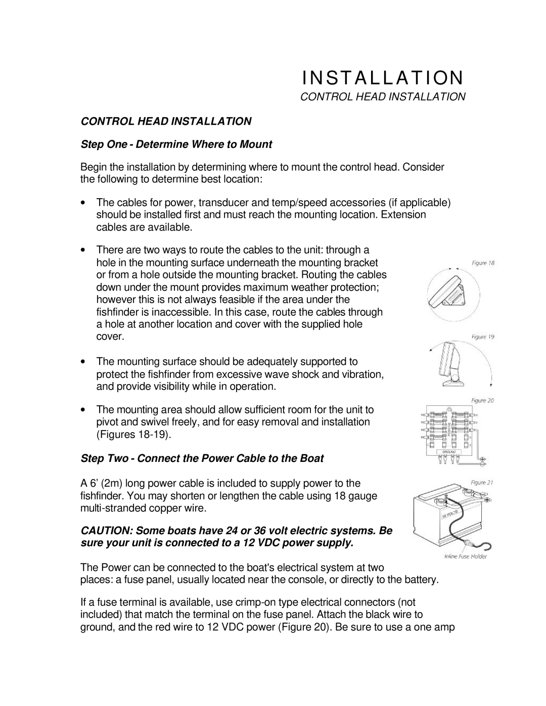
∙The mounting area should allow sufficient room for the unit to pivot and swivel freely, and for easy removal and installation (Figures
Step Two - Connect the Power Cable to the Boat
A 6’ (2m) long power cable is included to supply power to the fishfinder. You may shorten or lengthen the cable using 18 gauge
CAUTION: Some boats have 24 or 36 volt electric systems. Be sure your unit is connected to a 12 VDC power supply.
The Power can be connected to the boat's electrical system at two
places: a fuse panel, usually located near the console, or directly to the battery.
If a fuse terminal is available, use