INSTALLATION
CONTROL HEAD INSTALLATION
Step Five - Assembling the Connector Holder
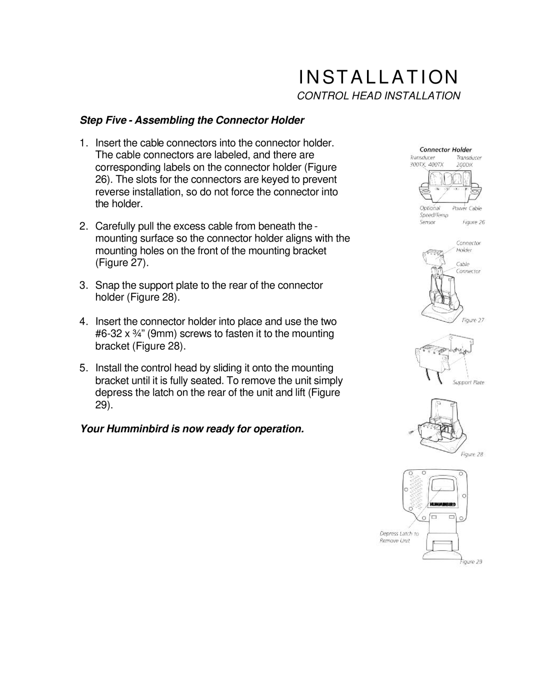
1.Insert the cable connectors into the connector holder. The cable connectors are labeled, and there are corresponding labels on the connector holder (Figure 26). The slots for the connectors are keyed to prevent reverse installation, so do not force the connector into the holder.
2.Carefully pull the excess cable from beneath the - mounting surface so the connector holder aligns with the mounting holes on the front of the mounting bracket (Figure 27).
3.Snap the support plate to the rear of the connector holder (Figure 28).
4.Insert the connector holder into place and use the two
5.Install the control head by sliding it onto the mounting bracket until it is fully seated. To remove the unit simply depress the latch on the rear of the unit and lift (Figure 29).