Setup & Installation 2
BASIC I/O TO BASIC I/O RS-422 MULTIDROP OR REPEATER
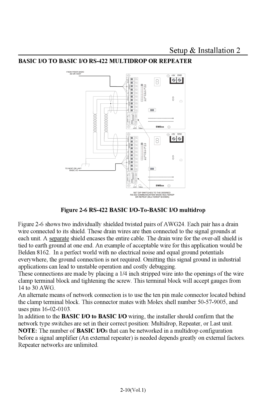
Figure 2-6 RS-422 BASIC I/O-To-BASIC I/O multidrop
Figure 2-6 shows two individually shielded twisted pairs of AWG24. Each pair has a drain wire connected to its shield. These drain wires are then connected to the signal grounds at each unit. A separate shield encases the entire cable. The drain wire for the over-all shield is tied to earth ground at one end. An example of acceptable wire for this application would be Belden 8162. In a perfect world with no electrical noise and equal ground potentials everywhere, the ground connection is not required. Omitting this signal ground in industrial applications can lead to unstable operation and costly debugging.
These connections are made by placing a 1/4 inch stripped wire into the openings of the wire clamp terminal block and tightening the screw. This terminal block will accept gauges from 14 to 30 AWG.
An alternate means of network connection is to use the ten pin male connector located behind the clamp terminal block. This connector mates with Molex shell number 50-57-9005, and uses pins 16-02-0103.
In addition to the BASIC I/O to BASIC I/O wiring, the installer should confirm that the network type switches are set in their correct position: Multidrop, Repeater, or Last unit. NOTE: The number of BASIC I/Os that can be networked in a multidrop configuration before a signal amplifier (An external repeater) is needed depends greatly on external factors. Repeater networks are unlimited.