Installation 2
Analog outputs:
Modules should NEVER be installed or removed while power is applied to the BASIC I/O
AD.
Note: Analog modules run hot to the touch.
Both voltage and current output modules provide their own isolated power output. This eliminates the need for external power supplies and insures electrical isolation between each output. This also makes it possible to wire voltage outputs in series to obtain larger voltage swings.
Module status indicators for analog outputs blink briefly as outputs are updated. It should be noted that the status indicator only follows the logic instruction to the modules and does not indicate the output status. Outputs can only be verified by observing the output device or by a multimeter or oscilloscope measurement.
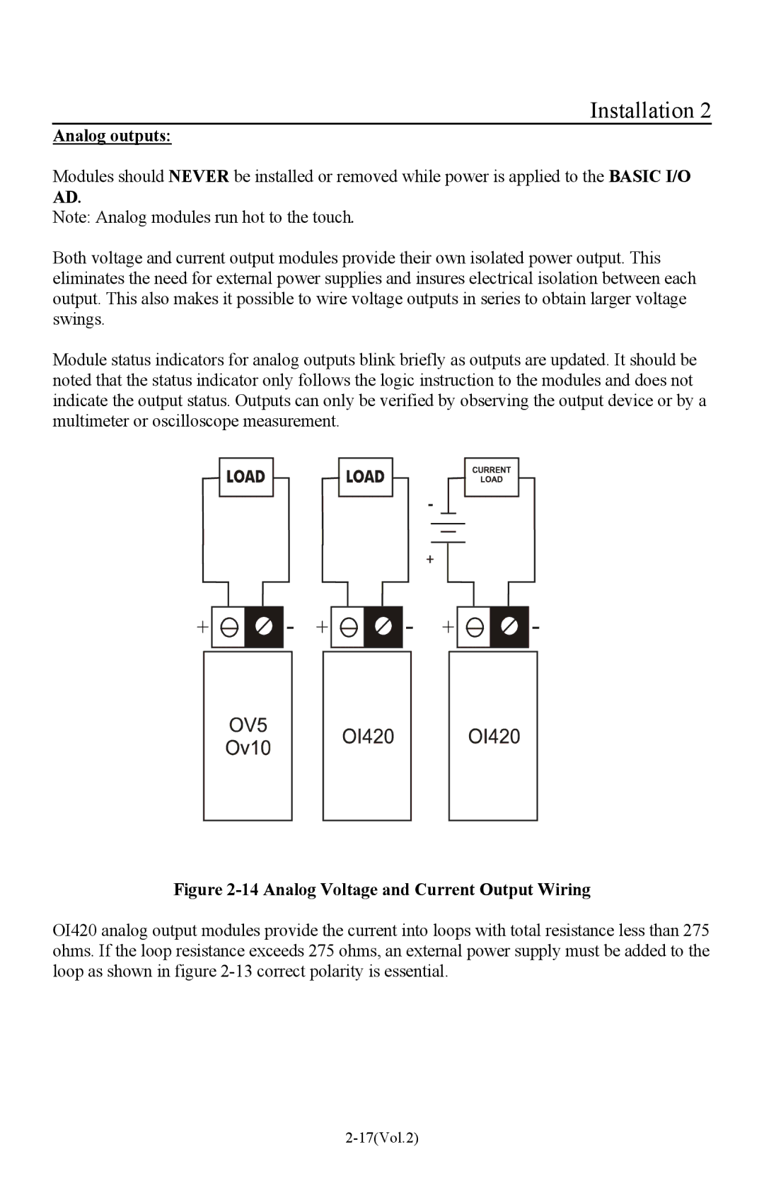
Figure 2-14 Analog Voltage and Current Output Wiring
OI420 analog output modules provide the current into loops with total resistance less than 275 ohms. If the loop resistance exceeds 275 ohms, an external power supply must be added to the loop as shown in figure