Setup & Installation 2
Digital Outputs:
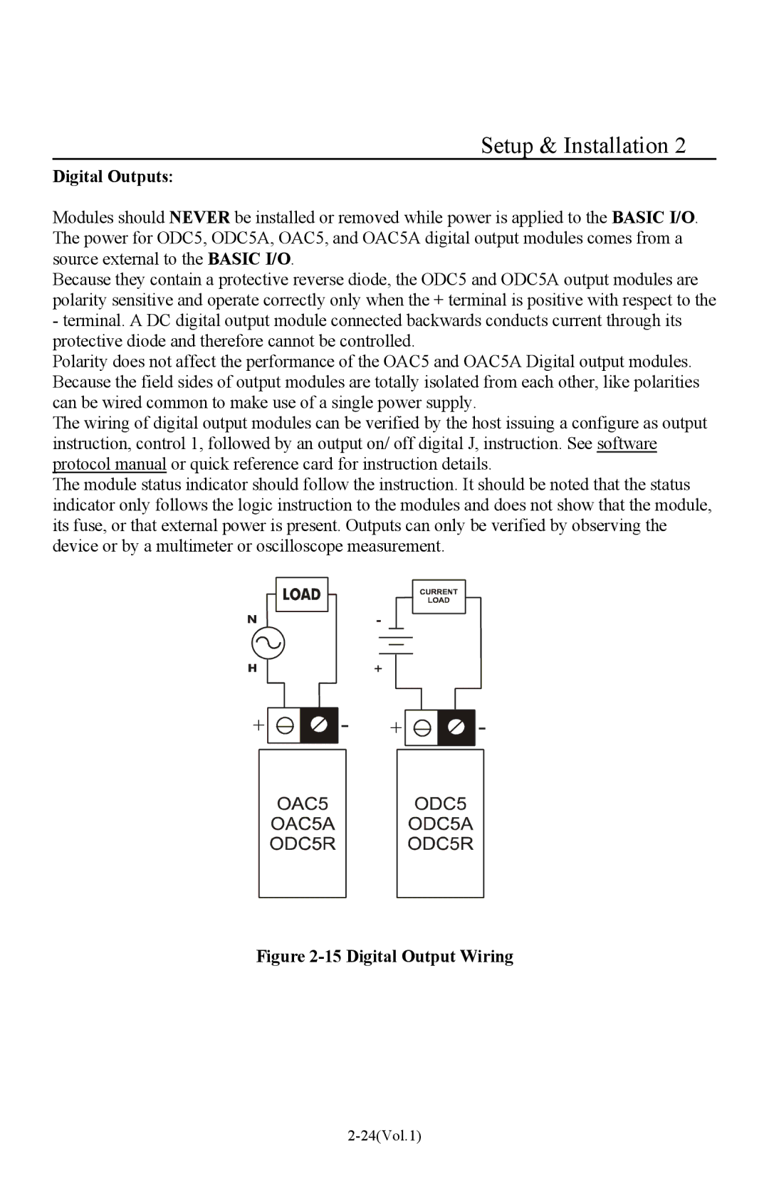
Modules should NEVER be installed or removed while power is applied to the BASIC I/O. The power for ODC5, ODC5A, OAC5, and OAC5A digital output modules comes from a source external to the BASIC I/O.
Because they contain a protective reverse diode, the ODC5 and ODC5A output modules are polarity sensitive and operate correctly only when the + terminal is positive with respect to the
-terminal. A DC digital output module connected backwards conducts current through its protective diode and therefore cannot be controlled.
Polarity does not affect the performance of the OAC5 and OAC5A Digital output modules. Because the field sides of output modules are totally isolated from each other, like polarities can be wired common to make use of a single power supply.
The wiring of digital output modules can be verified by the host issuing a configure as output instruction, control 1, followed by an output on/ off digital J, instruction. See software protocol manual or quick reference card for instruction details.
The module status indicator should follow the instruction. It should be noted that the status indicator only follows the logic instruction to the modules and does not show that the module, its fuse, or that external power is present. Outputs can only be verified by observing the device or by a multimeter or oscilloscope measurement.