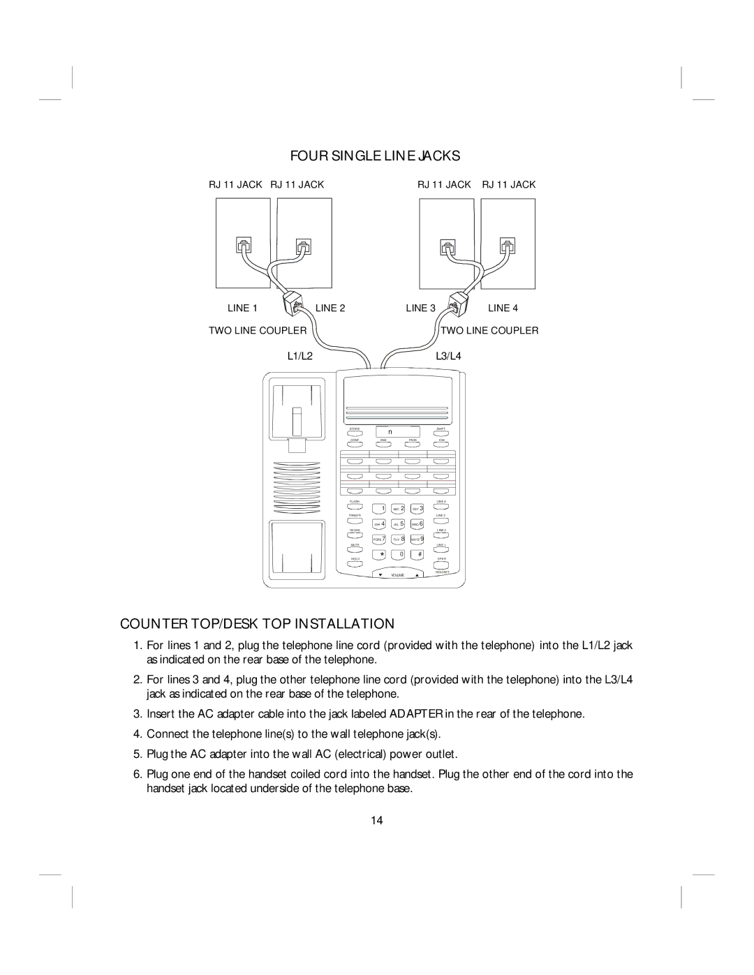
FOUR SINGLE LINE JACKS
RJ 11 JACK RJ 11 JACK | RJ 11 JACK RJ 11 JACK | ||||||||||||||||||||||||||||||||||
|
|
|
|
|
|
|
|
|
|
|
|
|
|
|
|
|
|
|
|
|
|
|
|
|
|
|
|
|
|
|
|
|
|
|
|
LINE 1 | LINE 2 | LINE 3 | LINE 4 |
TWO LINE COUPLER |
|
| TWO LINE COUPLER |
L3/L4
STORE |
| n | SHIFT |
|
|
| |
CONF | DND | PAGE | ICM |
FLASH
1
TRNSFR
GHI 4
REDIAL
![]() PQRS 7
PQRS 7
MUTE
HOLD |
| * |
|
|
|
q
ABC 2
JKL 5
TUV 8
0
VOLUME
LINE 4
DEF 3
LINE 3
MNO 6
LINE 2
WXYZ 9
LINE 1
#
SPKR
HEADSET
p
COUNTER TOP/DESK TOP INSTALLATION
1.For lines 1 and 2, plug the telephone line cord (provided with the telephone) into the L1/L2 jack as indicated on the rear base of the telephone.
2.For lines 3 and 4, plug the other telephone line cord (provided with the telephone) into the L3/L4 jack as indicated on the rear base of the telephone.
3.Insert the AC adapter cable into the jack labeled ADAPTER in the rear of the telephone.
4.Connect the telephone line(s) to the wall telephone jack(s).
5.Plug the AC adapter into the wall AC (electrical) power outlet.
6.Plug one end of the handset coiled cord into the handset. Plug the other end of the cord into the handset jack located underside of the telephone base.
14
