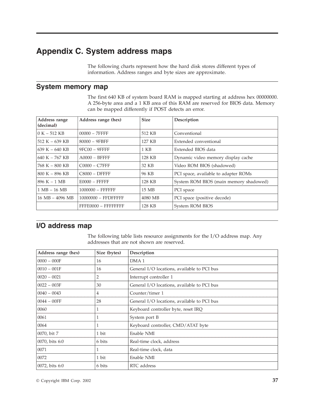
Appendix C. System address maps
The following charts represent how the hard disk stores different types of information. Address ranges and byte sizes are approximate.
System memory map
The first 640 KB of system board RAM is mapped starting at address hex 00000000. A
Address range | Address range (hex) | Size | Description | ||
(decimal) |
|
|
|
| |
|
|
|
| ||
0 K – 512 KB | 00000 – 7FFFF | 512 KB | Conventional | ||
|
|
|
|
| |
512 | K – 639 KB | 80000 – 9FBFF | 127 KB | Extended conventional | |
|
|
|
|
| |
639 | K – 640 KB | 9FC00 – 9FFFF | 1 KB | Extended BIOS data | |
|
|
|
|
| |
640 | K – 767 KB | A0000 – BFFFF | 128 KB | Dynamic video memory display cache | |
|
|
|
|
|
|
768 | K – 800 KB | C0000 – C7FFF | 32 | KB | Video ROM BIOS (shadowed) |
|
|
|
|
|
|
800 | K – 896 KB | C8000 – DFFFF | 96 | KB | PCI space, available to adapter ROMs |
|
|
|
|
| |
896 | K – 1 MB | E0000 – FFFFF | 128 KB | System ROM BIOS (main memory shadowed) | |
|
|
|
|
| |
1 MB – 16 MB | 1000000 – FFFFFF | 15 | MB | PCI space | |
|
|
|
| ||
16 MB – 4096 MB | 10000000 – FFDFFFFF | 4080 MB | PCI space (positive decode) | ||
|
|
|
|
| |
|
| FFFE0000 – FFFFFFFF | 128 KB | System ROM BIOS | |
|
|
|
|
|
|
I/O address map
The following table lists resource assignments for the I/O address map. Any addresses that are not shown are reserved.
Address range (hex) | Size (bytes) | Description | |
|
|
|
|
0000 | – 000F | 16 | DMA 1 |
|
|
|
|
0010 | – 001F | 16 | General I/O locations, available to PCI bus |
|
|
|
|
0020 | – 0021 | 2 | Interrupt controller 1 |
|
|
|
|
0022 | – 003F | 30 | General I/O locations, available to PCI bus |
|
|
|
|
0040 | – 0043 | 4 | Counter/timer 1 |
|
|
|
|
0044 | – 00FF | 28 | General I/O locations, available to PCI bus |
|
|
|
|
0060 |
| 1 | Keyboard controller byte, reset IRQ |
|
|
|
|
0061 |
| 1 | System port B |
|
|
|
|
0064 |
| 1 | Keyboard controller, CMD/ATAT byte |
|
|
| |
0070, bit 7 | 1 bit | Enable NMI | |
|
|
| |
0070, bits 6:0 | 6 bits | ||
|
|
|
|
0071 |
| 1 | |
|
|
|
|
0072 |
| 1 bit | Enable NMI |
|
|
| |
0072, bits 6:0 | 6 bits | RTC address | |
|
|
|
|
© Copyright IBM Corp. 2002 | 37 |