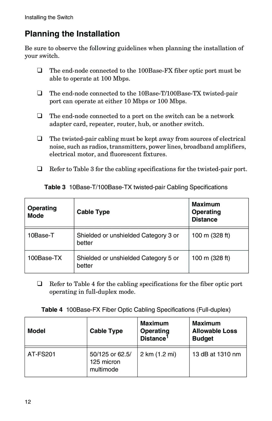
AT-FS202, AT-FS202SC/FS3, AT-FS201, AT-FS202SC/FS1, AT-FS202SC/FS4 specifications
The IBM AT-FS202 series includes a range of compact Ethernet switches designed to meet the needs of evolving network environments. These models, namely the AT-FS202SC/FS4, AT-FS202SC/FS2, AT-FS202, AT-FS202SC/FS3, and AT-FS201, offer a blend of performance, flexibility, and reliability tailored for small to medium-sized networks or edge installations.One of the standout features across these models is their support for both copper and fiber connectivity. The AT-FS202SC series specifically supports various transceiver options, allowing network administrators to choose the appropriate media type for their deployments. This versatility ensures that organizations can utilize their existing infrastructure while preparing for future upgrades.
In terms of performance, these switches provide wire-speed forwarding, enabling seamless data transfer and minimizing latency. With auto-sensing ports, they automatically detect the connected device and adjust to the necessary speed, whether it be 10/100/1000 Mbps. This ensures efficient operation within diverse environments, accommodating both legacy and modern devices without compromising on speed.
Security is an essential consideration for any network equipment, and the IBM AT-FS202 series is no exception. The switches include features such as port-based authentication and support for VLANs, which enhance network segmentation and isolate traffic flows. These security measures help protect sensitive data and restrict access to unauthorized users.
Management capabilities are another significant characteristic of the AT-FS202 series. These switches come equipped with management interfaces that allow for configuration, monitoring, and troubleshooting. The ability to manage network traffic effectively aids in sustaining optimal performance and quick resolution of potential issues.
Power consumption is optimized across the IBM AT-FS202 series, ensuring that deployment of these switches aligns with energy efficiency goals. This is particularly beneficial for businesses concerned with operational costs and environmental impact.
Overall, the IBM AT-FS202SC/FS4, AT-FS202SC/FS2, AT-FS202, AT-FS202SC/FS3, and AT-FS201 are robust solutions suited for diverse networking needs. Their combination of flexible connectivity options, performance efficiency, security features, and management capabilities position them as valuable assets for network administrators looking to build a resilient infrastructure in today's dynamic technological landscape.
