Table 32. Removal steps of LCD rear cover, wireless LAN antenna cables, and integrated camera (continued)
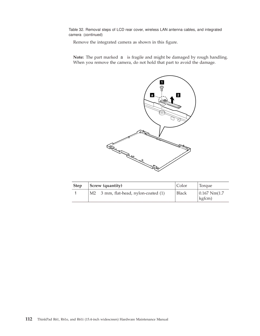
Remove the integrated camera as shown in this figure.
Note: The part marked is fragile and might be damaged by rough handling. When you remove the camera, do not hold that part to avoid the damage.
1
a
2
Step | Screw (quantity) | Color | Torque |
|
|
|
|
| M2 ⋅ 3 mm, | Black | 0.167 Nm(1.7 |
|
|
| kgfcm) |
|
|
|
|
112ThinkPad R61, R61e, and R61i