4-5 PORT ALLOCATIONS
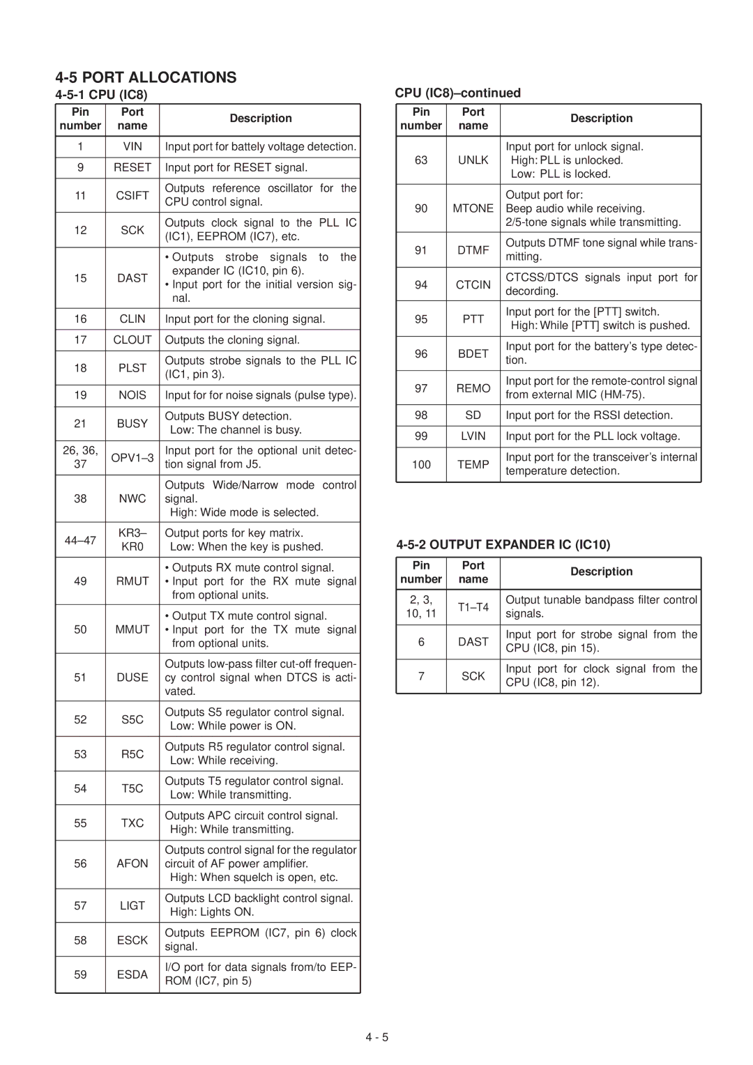
4-5-1 CPU (IC8)
Pin | Port | Description |
|
| ||
number | name |
|
| |||
|
|
|
| |||
|
|
| ||||
1 | VIN | Input port for battely voltage detection. | ||||
|
|
|
|
| ||
9 | RESET | Input port for RESET signal. |
|
| ||
|
|
|
|
|
| |
11 | CSIFT | Outputs reference | oscillator | for | the | |
CPU control signal. |
|
|
| |||
|
|
|
|
| ||
|
|
|
|
| ||
12 | SCK | Outputs clock signal to the | PLL | IC | ||
(IC1), EEPROM (IC7), etc. |
|
| ||||
|
|
|
| |||
|
|
|
|
|
| |
|
| • Outputs strobe | signals | to | the | |
15 | DAST | expander IC (IC10, pin 6). |
|
| ||
• Input port for the initial version sig- | ||||||
|
| |||||
|
| nal. |
|
|
| |
|
|
|
| |||
16 | CLIN | Input port for the cloning signal. |
| |||
|
|
|
|
| ||
17 | CLOUT | Outputs the cloning signal. |
|
| ||
|
|
| ||||
18 | PLST | Outputs strobe signals to the PLL IC | ||||
(IC1, pin 3). |
|
|
| |||
|
|
|
|
| ||
|
|
| ||||
19 | NOIS | Input for for noise signals (pulse type). | ||||
|
|
|
|
| ||
21 | BUSY | Outputs BUSY detection. |
|
| ||
Low: The channel is busy. |
|
| ||||
|
|
|
| |||
|
|
| ||||
26, 36, | Input port for the optional unit detec- | |||||
37 | tion signal from J5. |
|
|
| ||
|
|
|
| |||
|
| Outputs Wide/Narrow mode | control | |||
38 | NWC | signal. |
|
|
| |
|
| High: Wide mode is selected. |
|
| ||
|
|
|
|
| ||
KR3– | Output ports for key matrix. |
|
| |||
KR0 | Low: When the key is pushed. |
| ||||
|
| |||||
|
|
|
| |||
|
| • Outputs RX mute control signal. |
| |||
49 | RMUT | • Input port for the RX mute signal | ||||
|
| from optional units. |
|
| ||
|
|
|
| |||
|
| • Output TX mute control signal. |
| |||
50 | MMUT | • Input port for the TX mute signal | ||||
|
| from optional units. |
|
| ||
|
|
| ||||
|
| Outputs | ||||
51 | DUSE | cy control signal when DTCS is acti- | ||||
|
| vated. |
|
|
| |
|
|
| ||||
52 | S5C | Outputs S5 regulator control signal. | ||||
Low: While power is ON. |
|
| ||||
|
|
|
| |||
|
|
| ||||
53 | R5C | Outputs R5 regulator control signal. | ||||
Low: While receiving. |
|
| ||||
|
|
|
| |||
|
|
| ||||
54 | T5C | Outputs T5 regulator control signal. | ||||
Low: While transmitting. |
|
| ||||
|
|
|
| |||
|
|
|
| |||
55 | TXC | Outputs APC circuit control signal. |
| |||
High: While transmitting. |
|
| ||||
|
|
|
| |||
|
|
| ||||
|
| Outputs control signal for the regulator | ||||
56 | AFON | circuit of AF power amplifier. |
|
| ||
|
| High: When squelch is open, etc. |
| |||
|
|
| ||||
57 | LIGT | Outputs LCD backlight control signal. | ||||
High: Lights ON. |
|
|
| |||
|
|
|
|
| ||
|
|
| ||||
58 | ESCK | Outputs EEPROM (IC7, pin 6) clock | ||||
signal. |
|
|
| |||
|
|
|
|
| ||
|
|
| ||||
59 | ESDA | I/O port for data signals from/to EEP- | ||||
ROM (IC7, pin 5) |
|
|
| |||
|
|
|
|
| ||
|
|
|
|
|
| |
CPU (IC8)–continued
Pin | Port | Description | |
number | name | ||
| |||
|
|
| |
|
| Input port for unlock signal. | |
63 | UNLK | High: PLL is unlocked. | |
|
| Low: PLL is locked. | |
|
|
| |
|
| Output port for: | |
90 | MTONE | Beep audio while receiving. | |
|
| ||
|
|
| |
91 | DTMF | Outputs DTMF tone signal while trans- | |
mitting. | |||
|
| ||
|
|
| |
94 | CTCIN | CTCSS/DTCS signals input port for | |
decording. | |||
|
| ||
|
|
| |
95 | PTT | Input port for the [PTT] switch. | |
High: While [PTT] switch is pushed. | |||
|
| ||
|
|
| |
96 | BDET | Input port for the battery’s type detec- | |
tion. | |||
|
| ||
|
|
| |
97 | REMO | Input port for the | |
from external MIC | |||
|
| ||
|
|
| |
98 | SD | Input port for the RSSI detection. | |
|
|
| |
99 | LVIN | Input port for the PLL lock voltage. | |
|
|
| |
100 | TEMP | Input port for the transceiver’s internal | |
temperature detection. | |||
|
| ||
|
|
|
4-5-2 OUTPUT EXPANDER IC (IC10)
Pin | Port | Description | |
number | name | ||
| |||
|
|
| |
2, 3, | Output tunable bandpass filter control | ||
10, 11 | signals. | ||
| |||
|
|
| |
6 | DAST | Input port for strobe signal from the | |
CPU (IC8, pin 15). | |||
|
| ||
|
|
| |
7 | SCK | Input port for clock signal from the | |
CPU (IC8, pin 12). | |||
|
| ||
|
|
|
4 - 5