5-3 SOFTWARE ADJUSTMENT
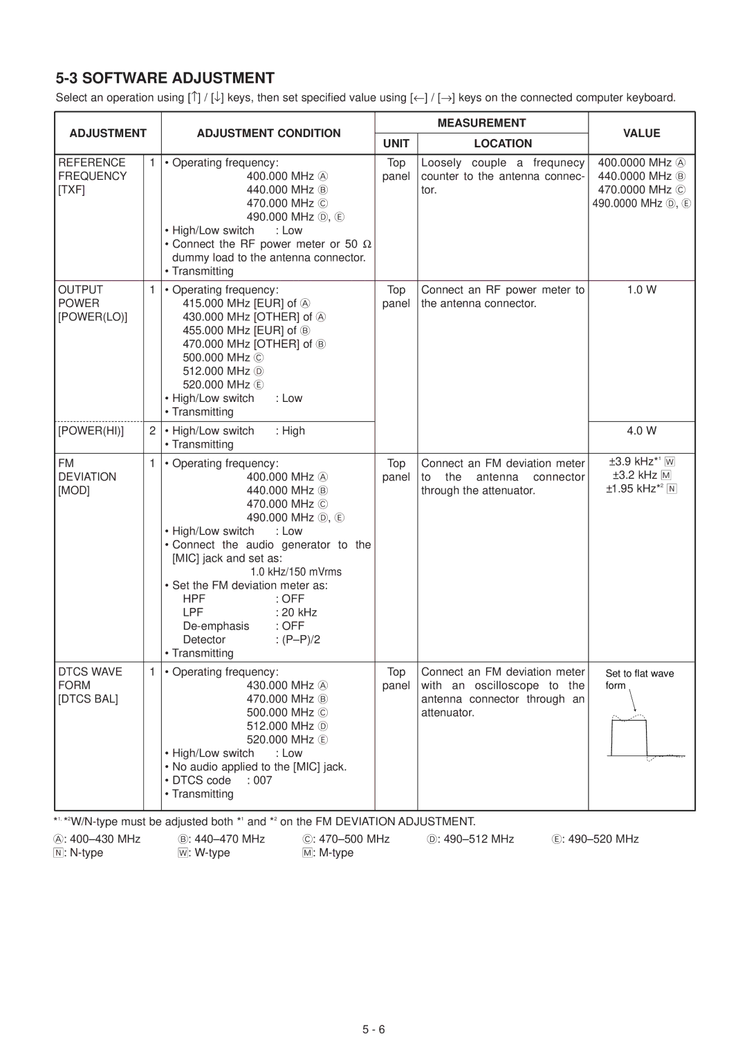
Select an operation using [↑] / [↓] keys, then set specified value using [←] / [→] keys on the connected computer keyboard.
ADJUSTMENT |
| ADJUSTMENT CONDITION |
| MEASUREMENT | VALUE | |
| UNIT | LOCATION | ||||
|
|
|
|
| ||
|
|
|
|
|
|
|
REFERENCE | 1 | • Operating frequency: |
| Top | Loosely couple a frequnecy | 400.0000 MHz A |
FREQUENCY |
| 400.000 | MHz A | panel | counter to the antenna connec- | 440.0000 MHz B |
[TXF] |
| 440.000 | MHz B |
| tor. | 470.0000 MHz C |
|
| 470.000 | MHz C |
|
| 490.0000 MHz D, E |
|
| 490.000 | MHz D, E |
|
|
|
|
| • High/Low switch : Low |
|
|
| |
•Connect the RF power meter or 50 Ω dummy load to the antenna connector.
•Transmitting
OUTPUT | 1 | • Operating frequency: |
| Top | Connect an RF power meter to | 1.0 W |
| ||
POWER |
| 415.000 | MHz [EUR] of A | panel | the antenna connector. |
|
| ||
[POWER(LO)] |
| 430.000 | MHz [OTHER] of A |
|
|
|
| ||
|
| 455.000 | MHz [EUR] of B |
|
|
|
| ||
|
| 470.000 | MHz [OTHER] of B |
|
|
|
| ||
|
| 500.000 | MHz C |
|
|
|
|
|
|
|
| 512.000 | MHz D |
|
|
|
|
|
|
|
| 520.000 | MHz E |
|
|
|
|
|
|
|
| • High/Low switch | : Low |
|
|
|
| ||
|
| • Transmitting |
|
|
|
|
|
| |
|
|
|
|
|
|
|
| ||
[POWER(HI)] | 2 | • High/Low switch | : High |
|
| 4.0 W |
| ||
|
| • Transmitting |
|
|
|
|
|
| |
|
|
|
|
|
|
|
| ||
FM | 1 | • Operating frequency: |
| Top | Connect an FM deviation meter | ±3.9 kHz*1 | „ | ||
DEVIATION |
|
| 400.000 | MHz A | panel to the antenna connector | ±3.2 kHz ˜ | |||
[MOD] |
|
| 440.000 | MHz B |
| through the attenuator. | ±1.95 kHz*2 | ˆ | |
|
|
| 470.000 | MHz C |
|
|
|
| |
|
|
| 490.000 | MHz D, E |
|
|
|
| |
|
| • High/Low switch | : Low |
|
|
|
| ||
•Connect the audio generator to the [MIC] jack and set as:
1.0kHz/150 mVrms
•Set the FM deviation meter as:
| HPF |
| : OFF |
|
|
|
|
| LPF |
| : 20 kHz |
|
|
|
|
| : OFF |
|
|
|
| ||
| Detector |
| : |
|
|
|
|
| • Transmitting |
|
|
|
|
|
|
|
|
|
|
|
| ||
DTCS WAVE | 1 • Operating frequency: | Top Connect an FM deviation meter | Set to flat wave | ||||
FORM |
| 430.000 MHz A | panel with an oscilloscope to the | form | |||
[DTCS BAL] |
| 470.000 MHz B | antenna connector through an |
|
|
| |
|
| 500.000 MHz C | attenuator. |
|
|
| |
|
| 512.000 MHz D |
|
|
|
| |
|
| 520.000 MHz E |
|
|
|
| |
| • High/Low switch | : Low |
|
|
|
| |
|
|
|
|
| |||
| • No audio applied to the [MIC] jack. |
|
|
|
| ||
| • DTCS code | : 007 |
|
|
|
|
|
| • Transmitting |
|
|
|
|
|
|
*1, |
| |||
A: | B: | C: | D: | E: |
ˆ: | „: | ˜: |
|
|
5 - 6