POptional UT-96R or UT-119H installation
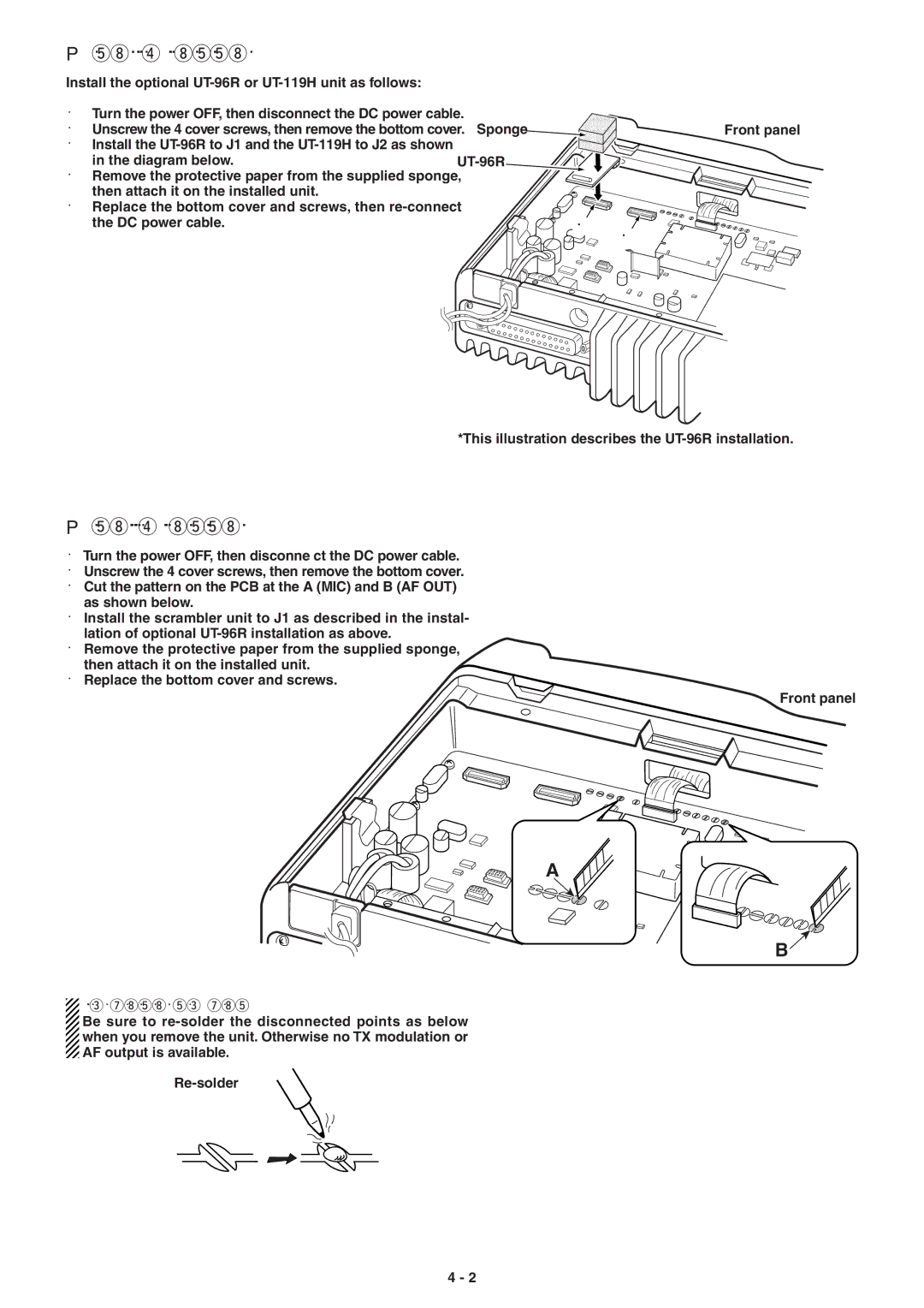
Install the optional UT-96R or UT-119H unit as follows:
qTurn the power OFF, then disconnect the DC power cable.
wUnscrew the 4 cover screws, then remove the bottom cover.
eInstall the
rRemove the protective paper from the supplied sponge, then attach it on the installed unit.
tReplace the bottom cover and screws, then
Sponge | Front panel |
|
J1
J2
*This illustration describes the
POptional UT-109R or UT-110R installation
q Turn the power OFF, then disconne ct the DC power cable. w Unscrew the 4 cover screws, then remove the bottom cover. e Cut the pattern on the PCB at the A (MIC) and B (AF OUT)
as shown below.
r Install the scrambler unit to J1 as described in the instal- lation of optional
t Remove the protective paper from the supplied sponge, then attach it on the installed unit.
y Replace the bottom cover and screws.
Front panel
A
B![]()
![]() NOTE: When uninstalling the unit
NOTE: When uninstalling the unit
![]() Be sure to
Be sure to
when you remove the unit. Otherwise no TX modulation or
![]() AF output is available.
AF output is available.
4 - 2