4-3-2 VCO CIRCUIT (MAIN UNIT)
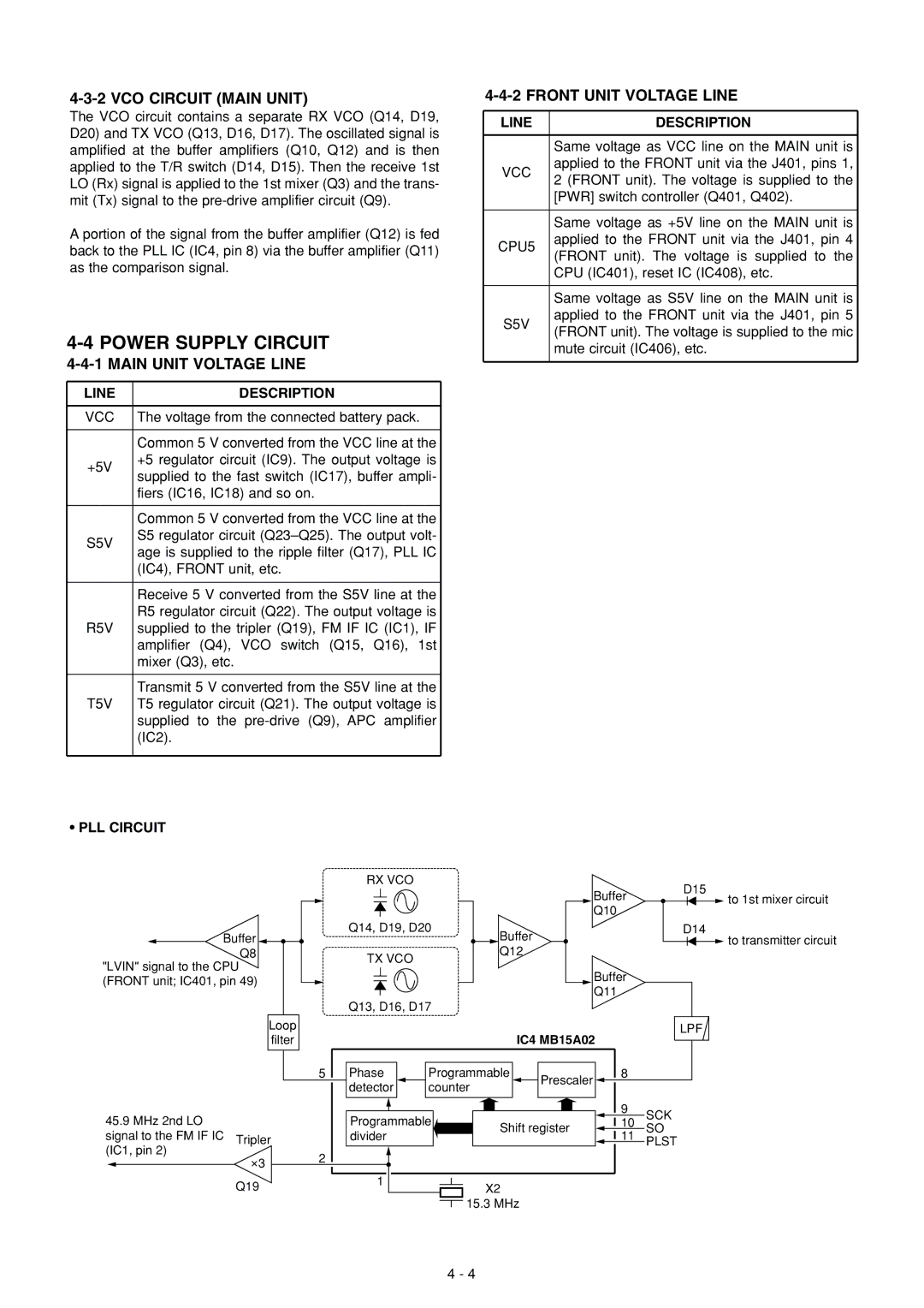
The VCO circuit contains a separate RX VCO (Q14, D19, D20) and TX VCO (Q13, D16, D17). The oscillated signal is amplified at the buffer amplifiers (Q10, Q12) and is then applied to the T/R switch (D14, D15). Then the receive 1st LO (Rx) signal is applied to the 1st mixer (Q3) and the trans- mit (Tx) signal to the
A portion of the signal from the buffer amplifier (Q12) is fed back to the PLL IC (IC4, pin 8) via the buffer amplifier (Q11) as the comparison signal.
4-4 POWER SUPPLY CIRCUIT
4-4-1 MAIN UNIT VOLTAGE LINE
LINE | DESCRIPTION | |
|
| |
VCC | The voltage from the connected battery pack. | |
|
| |
| Common 5 V converted from the VCC line at the | |
+5V | +5 regulator circuit (IC9). The output voltage is | |
supplied to the fast switch (IC17), buffer ampli- | ||
| ||
| fiers (IC16, IC18) and so on. | |
|
| |
| Common 5 V converted from the VCC line at the | |
S5V | S5 regulator circuit | |
age is supplied to the ripple filter (Q17), PLL IC | ||
| ||
| (IC4), FRONT unit, etc. | |
|
| |
| Receive 5 V converted from the S5V line at the | |
| R5 regulator circuit (Q22). The output voltage is | |
R5V | supplied to the tripler (Q19), FM IF IC (IC1), IF | |
| amplifier (Q4), VCO switch (Q15, Q16), 1st | |
| mixer (Q3), etc. | |
|
| |
| Transmit 5 V converted from the S5V line at the | |
T5V | T5 regulator circuit (Q21). The output voltage is | |
| supplied to the | |
| (IC2). | |
|
|
•PLL CIRCUIT
4-4-2 FRONT UNIT VOLTAGE LINE
LINE | DESCRIPTION | |
|
| |
| Same voltage as VCC line on the MAIN unit is | |
VCC | applied to the FRONT unit via the J401, pins 1, | |
2 (FRONT unit). The voltage is supplied to the | ||
| ||
| [PWR] switch controller (Q401, Q402). | |
|
| |
| Same voltage as +5V line on the MAIN unit is | |
CPU5 | applied to the FRONT unit via the J401, pin 4 | |
(FRONT unit). The voltage is supplied to the | ||
| ||
| CPU (IC401), reset IC (IC408), etc. | |
|
| |
| Same voltage as S5V line on the MAIN unit is | |
S5V | applied to the FRONT unit via the J401, pin 5 | |
(FRONT unit). The voltage is supplied to the mic | ||
| ||
| mute circuit (IC406), etc. | |
|
|
|
|
| RX VCO |
|
|
|
|
| D15 |
|
|
|
|
|
|
|
| Buffer | |
|
|
|
|
|
|
|
|
| |
|
|
|
|
|
|
|
| Q10 |
|
Buffer |
| Q14, D19, D20 |
| Buffer |
|
| D14 | ||
|
|
|
|
|
|
| |||
| Q8 |
| TX VCO |
|
| Q12 |
|
|
|
"LVIN" signal to the CPU |
|
|
|
|
|
|
| ||
|
|
|
|
|
| Buffer |
| ||
(FRONT unit; IC401, pin 49) |
|
|
|
|
|
|
| ||
|
|
|
|
|
| Q11 |
| ||
|
|
|
|
|
|
|
|
| |
|
|
| Q13, D16, D17 |
|
|
|
|
| |
| Loop |
|
|
|
| IC4 MB15A02 | LPF | ||
| filter |
|
|
|
|
| |||
|
| 5 | Phase | Programmable | Prescaler | 8 |
| ||
|
|
| detector | counter |
|
|
| ||
|
|
|
|
|
|
| |||
45.9 MHz 2nd LO |
|
| Programmable |
|
|
| 9 | SCK | |
|
|
| Shift register | 10 | |||||
|
|
| SO | ||||||
signal to the FM IF IC | Tripler |
| divider |
|
| 11 | |||
|
|
|
|
| PLST | ||||
(IC1, pin 2) |
|
|
|
|
|
|
| ||
3 | 2 |
|
|
|
|
|
|
| |
|
|
|
|
|
|
|
| ||
|
|
|
|
|
|
|
|
| |
| Q19 |
| 1 |
|
| X2 |
|
|
|
|
|
|
|
|
|
|
| ||
|
|
|
|
| 15.3 MHz |
|
|
| |
![]() to 1st mixer circuit
to 1st mixer circuit
![]() to transmitter circuit
to transmitter circuit
4 - 4