4-5 OTHER CIRCUITS
4-5-1 COMPOUNDER CIRCUIT (MAIN UNIT)
(1) IN CASE OF TRANSMITTING
The audio signals from the microphone are applied to the base band IC (IC10, pin 3) via microphone mute circuit (FRONT unit; IC406), microphone amplifier (IC407), etc. The signals are amplified at the amplifier section, and are then applied to the compressor circuit to compress the audio signals. The signals pass through (or bypass) scrambler section, and are then amplified at limiter amplifier section after being passed through the
(2) IN CASE OF RECEIVING
The demodulated AF signals from the IF IC are applied to the amplifier section of base band IC (IC10, pin 23), and then pass through the
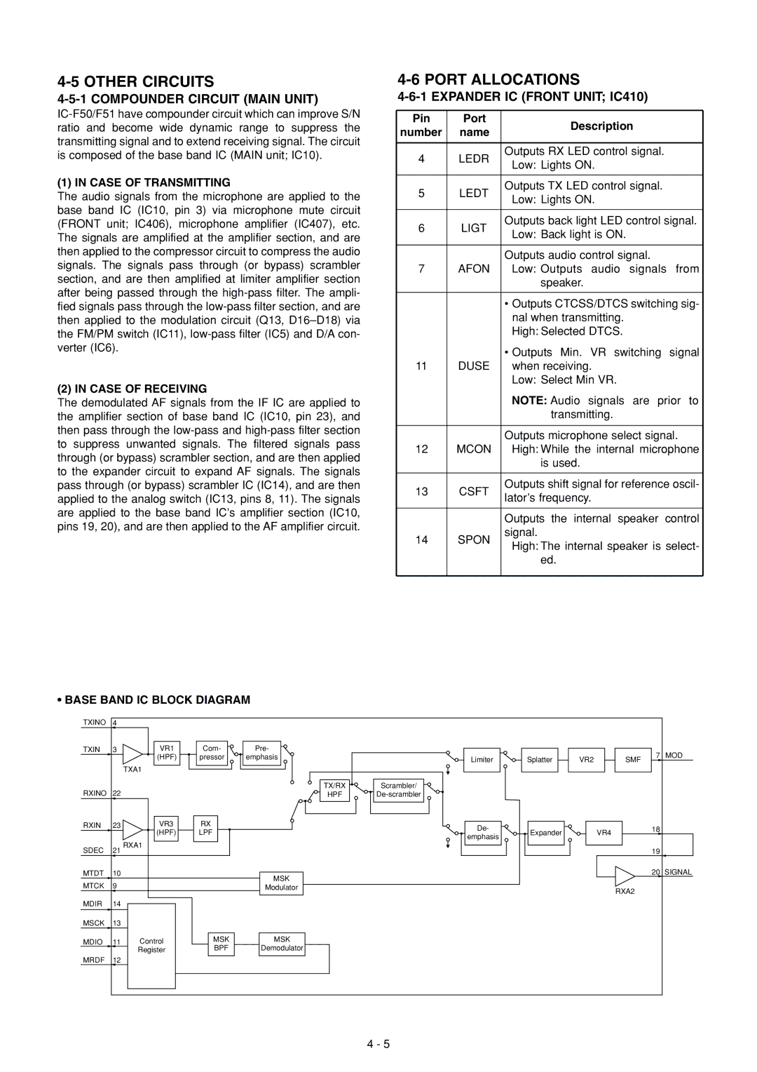
•BASE BAND IC BLOCK DIAGRAM
4-6 PORT ALLOCATIONS
4-6-1 EXPANDER IC (FRONT UNIT; IC410)
Pin | Port | Description | |
number | name | ||
| |||
|
|
| |
4 | LEDR | Outputs RX LED control signal. | |
Low: Lights ON. | |||
|
| ||
|
|
| |
5 | LEDT | Outputs TX LED control signal. | |
Low: Lights ON. | |||
|
| ||
|
|
| |
6 | LIGT | Outputs back light LED control signal. | |
Low: Back light is ON. | |||
|
| ||
|
|
| |
|
| Outputs audio control signal. | |
7 | AFON | Low: Outputs audio signals from | |
|
| speaker. | |
|
|
| |
|
| • Outputs CTCSS/DTCS switching sig- | |
|
| nal when transmitting. | |
|
| High: Selected DTCS. | |
|
| • Outputs Min. VR switching signal | |
11 | DUSE | when receiving. | |
|
| Low: Select Min VR. | |
|
| NOTE: Audio signals are prior to | |
|
| transmitting. | |
|
|
| |
|
| Outputs microphone select signal. | |
12 | MCON | High: While the internal microphone | |
|
| is used. | |
|
|
| |
13 | CSFT | Outputs shift signal for reference oscil- | |
lator’s frequency. | |||
|
| ||
|
|
| |
|
| Outputs the internal speaker control | |
14 | SPON | signal. | |
High: The internal speaker is select- | |||
|
| ||
|
| ed. | |
|
|
|
TXINO | 4 |
|
|
|
|
TXIN | 3 | VR1 |
|
| (HPF) |
| TXA1 |
|
|
| |
RXINO | 22 |
|
|
|
|
RXIN | 23 | VR3 |
|
| (HPF) |
SDEC | 21 RXA1 |
|
| ||
MTDT | 10 |
|
MTCK | 9 |
|
MDIR 14
MSCK 13
MDIO 11 Control
Register
MRDF 12
Com-
pressor
RX
LPF
MSK
BPF
Pre-
emphasis
TX/RX
HPF
MSK
Modulator
MSK
Demodulator
Limiter | Splatter | VR2 | SMF | 7 MOD |
|
Scrambler/
De- | Expander | VR4 | 18 |
emphasis |
| ||
|
|
|
19
20 SIGNAL
RXA2
4 - 5