5-2 SOFTWARE ADJUSTMENTS (TRANSMITTING)
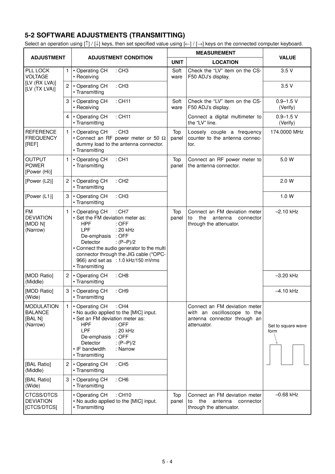
Select an operation using [↑] / [↓] keys, then set specified value using [←] / [→] keys on the connected computer keyboard.
ADJUSTMENT |
| ADJUSTMENT CONDITION |
|
| MEASUREMENT | VALUE | |||
| UNIT |
|
| LOCATION | |||||
|
|
|
|
|
|
| |||
PLL LOCK | 1 | • Operating CH | : CH3 | Soft | Check the “LV” item on the CS- | 3.5 V | |||
VOLTAGE |
| • Receiving |
| ware | F50 ADJ’s display. |
|
| ||
[LV (RX LVA)] | 2 | • Operating CH | : CH3 |
|
|
|
|
| 3.5 V |
[LV (TX LVA)] |
|
|
|
|
| ||||
| • Transmitting |
|
|
|
|
|
|
| |
|
|
|
|
|
|
|
|
| |
| 3 | • Operating CH | : CH11 | Soft | Check the “LV” item on the CS- | ||||
|
| • Receiving |
| ware | F50 ADJ’s display. |
| (Verify) | ||
| 4 | • Operating CH | : CH11 |
| Connect a digital multimeter to | ||||
|
| • Transmitting |
|
| the “LV” line. |
| (Verify) | ||
REFERENCE | 1 | • Operating CH | : CH3 | Top | Loosely | couple a | frequency | 174.0000 MHz | |
FREQUENCY |
| • Connect an RF power meter or 50 Ω | panel | counter to the antenna connec- |
| ||||
[REF] |
| dummy load to the antenna connector. |
| tor. |
|
|
|
| |
|
| • Transmitting |
|
|
|
|
|
|
|
OUTPUT | 1 | • Operating CH | : CH1 | Top | Connect an RF power meter to | 5.0 W | |||
POWER |
| • Transmitting |
| panel | the antenna connector. |
| |||
[Power (Hi)] |
|
|
|
|
|
|
|
|
|
[Power (L2)] | 2 | • Operating CH | : CH2 |
|
|
|
|
| 2.0 W |
|
| • Transmitting |
|
|
|
|
|
|
|
[Power (L1)] | 3 | • Operating CH | : CH3 |
|
|
|
|
| 1.0 W |
|
| • Transmitting |
|
|
|
|
|
|
|
FM | 1 | • Operating CH | : CH7 | Top | Connect an FM deviation meter | ±2.10 kHz | |||
DEVIATION |
| • Set the FM deviation meter as: | panel | to | the | antenna | connector |
| |
[MOD N] |
| HPF | : OFF |
| through the attenuator. |
| |||
(Narrow) |
| LPF | : 20 kHz |
|
|
|
|
|
|
|
| : OFF |
|
|
|
|
|
| |
|
| Detector | : |
|
|
|
|
|
|
|
| • Connect the audio generator to the multi |
|
|
|
|
|
| |
|
| connector through the JIG cable (*OPC- |
|
|
|
|
|
| |
|
| 966) and set as | : 1.0 kHz/150 mVrms |
|
|
|
|
|
|
|
| • Transmitting |
|
|
|
|
|
|
|
[MOD Ratio] | 2 | • Operating CH | : CH8 |
|
|
|
|
| ±3.20 kHz |
(Middle) |
| • Transmitting |
|
|
|
|
|
|
|
[MOD Ratio] | 3 | • Operating CH | : CH9 |
|
|
|
|
| ±4.10 kHz |
(Wide) |
| • Transmitting |
|
|
|
|
|
|
|
MODULATION | 1 | • Operating CH | : CH4 |
| Connect an FM deviation meter |
| |||
BALANCE |
| • No audio applied to the [MIC] input. |
| with an oscilloscope to the |
| ||||
[BAL N] |
| • Set an FM deviation meter as: |
| antenna | connector | through an |
| ||
(Narrow) |
| HPF | : OFF |
| attenuator. |
| Set to square wave | ||
|
| LPF | : 20 kHz |
|
|
|
|
| form |
|
| : OFF |
|
|
|
|
|
| |
|
| Detector | : |
|
|
|
|
|
|
|
| • IF bandwidth | : Narrow |
|
|
|
|
|
|
|
| • Transmitting |
|
|
|
|
|
|
|
[BAL Ratio] | 2 | • Operating CH | : CH5 |
|
|
|
|
|
|
(Middle) |
| • Transmitting |
|
|
|
|
|
|
|
[BAL Ratio] | 3 | • Operating CH | : CH6 |
|
|
|
|
|
|
(Wide) |
| • Transmitting |
|
|
|
|
|
|
|
CTCSS/DTCS |
| • Operating CH | : CH10 | Top | Connect an FM deviation meter | ±0.68 kHz | |||
DEVIATION |
| • No audio applied to the [MIC] input. | panel | to | the | antenna | connector |
| |
[CTCS/DTCS] |
| • Transmitting |
|
| through the attenuator. |
| |||
5 - 4