5-3 SOFTWARE ADJUSTMENT
Select an operation using [↑] / [↓] keys, then set specified value using [←] / [→] keys on the connected computer keyboard.
ADJUSTMENT |
| ADJUSTMENT CONDITION |
|
| MEASUREMENT |
| VALUE |
| ||
| UNIT |
|
| LOCATION |
| |||||
|
|
|
|
|
|
|
| |||
REFERENCE | 1 • Operating freq. : 174.000 MHz | Rear | Loosely | couple a | frequnecy | 174.0000 MHz | ||||
FREQUENCY |
| • Output power | : Low1 | panel | counter to the antenna connec- |
|
| |||
[TXF] |
| • Connect the RF power meter or 50 Ω |
| tor. |
|
|
|
|
| |
|
| dummy load to the antenna connector. |
|
|
|
|
|
|
| |
|
| • Transmitting |
|
|
|
|
|
|
|
|
OUTPUT | 1 • Operating freq. : 155.000 MHz | Rear | Connect an RF power meter to | 25.0 W [25 W] | ||||||
POWER |
| • Output power | : High | panel | the antenna connector. | 50.0 W [50 W] | ||||
[Power (Hi)] |
| • Transmitting |
|
|
|
|
|
|
|
|
[Power (L2)] | 2 | • Output power | : Low2 |
|
|
|
|
| 10.0 W [25W] | |
|
| • Transmitting |
|
|
|
|
|
| 25.0 W [50 W] | |
[Power (L1)] | 3 | • Output power | : Low1 |
|
|
|
|
| 2.5 W [25W] | |
|
| • Transmitting |
|
|
|
|
|
| 5.0 W [50 W] | |
FM | 1 • Operating freq. : 155.000 MHz | Rear | Connect an FM deviation meter | ±4.1 kHz | [N/W] | |||||
DEVIATION |
| • Output power | : Low1 | panel | to | the | antenna | connector | ±3.3 kHz | [N/M] |
[MOD W] |
| • IF bandwidth | : Wide |
| through the attenuator. |
|
| |||
|
| • Connect an audio generator to the [MIC] |
|
|
|
|
|
|
| |
|
| jack through the JIG cable and set as: |
|
|
|
|
|
|
| |
|
| 1.0 kHz/40 mVrms |
|
|
|
|
|
|
| |
|
| • Set an FM deviation meter as: |
|
|
|
|
|
|
| |
|
| HPF | : OFF |
|
|
|
|
|
|
|
|
| LPF | : 20 kHz |
|
|
|
|
|
|
|
|
|
|
|
|
|
|
|
| ||
|
| Detector | : |
|
|
|
|
|
|
|
|
| • Transmitting |
|
|
|
|
|
|
|
|
[MOD Ratio] | 2 | • IF bandwidth | : Narrow |
|
|
|
|
| ±2.1 kHz | |
|
| • Transmitting |
|
|
|
|
|
|
|
|
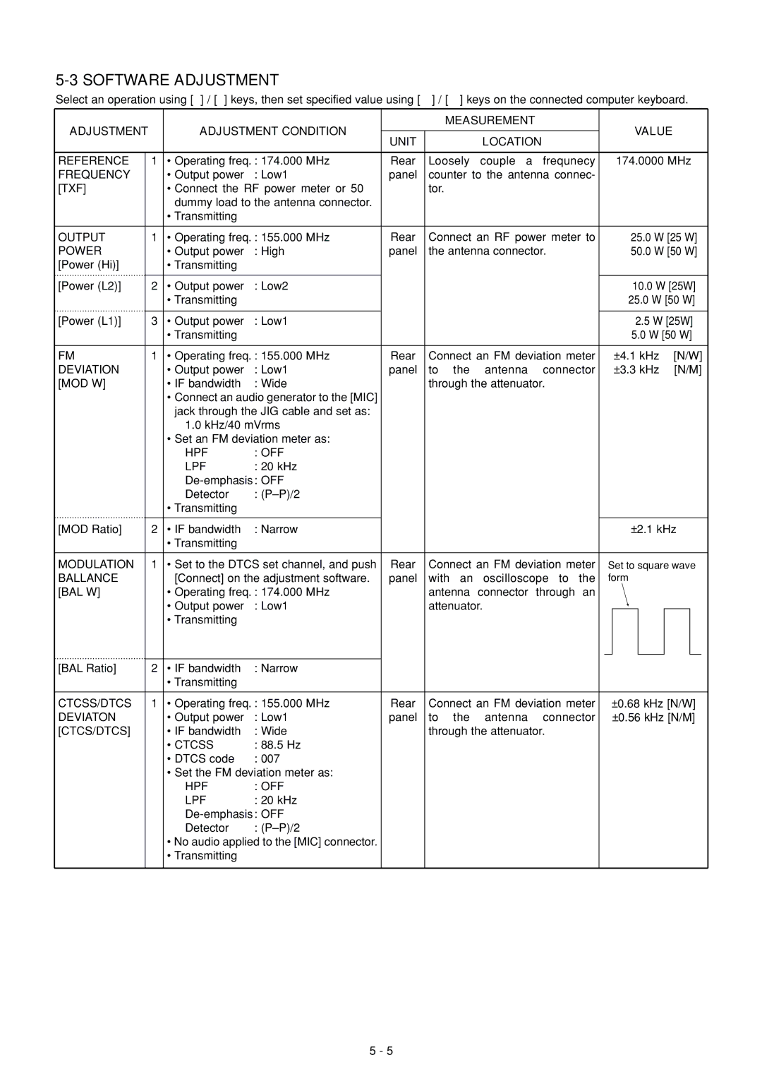
MODULATION | 1 • Set to the DTCS set channel, and push | Rear | Connect an FM deviation meter | Set to square wave | ||||||
BALLANCE |
| [Connect] on the adjustment software. | panel | with an oscilloscope to the | form |
| ||||
[BAL W] |
| • Operating freq. : 174.000 MHz |
| antenna | connector | through an |
|
| ||
|
| • Output power | : Low1 |
| attenuator. |
|
|
| ||
|
| • Transmitting |
|
|
|
|
|
|
|
|
[BAL Ratio] | 2 | • IF bandwidth | : Narrow |
|
|
|
|
|
|
|
|
| • Transmitting |
|
|
|
|
|
|
|
|
CTCSS/DTCS | 1 • Operating freq. : 155.000 MHz | Rear | Connect an FM deviation meter | ±0.68 kHz [N/W] | ||||||
DEVIATON |
| • Output power | : Low1 | panel | to | the | antenna | connector | ±0.56 kHz [N/M] | |
[CTCS/DTCS] |
| • IF bandwidth | : Wide |
| through the attenuator. |
|
| |||
|
| • CTCSS | : 88.5 Hz |
|
|
|
|
|
|
|
|
| • DTCS code | : 007 |
|
|
|
|
|
|
|
|
| • Set the FM deviation meter as: |
|
|
|
|
|
|
| |
|
| HPF | : OFF |
|
|
|
|
|
|
|
|
| LPF | : 20 kHz |
|
|
|
|
|
|
|
|
|
|
|
|
|
|
|
| ||
|
| Detector | : |
|
|
|
|
|
|
|
|
| • No audio applied to the [MIC] connector. |
|
|
|
|
|
|
| |
|
| • Transmitting |
|
|
|
|
|
|
|
|
5 - 5