CPU-Continued
Pin | Port | Description | |
number | name | ||
| |||
|
|
| |
|
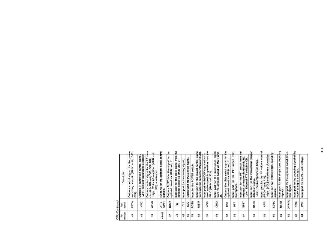
| Outputs control signal for the power | |
41 | PWON | switching circuit (MAIN unit; Q23, | |
|
| Q24). | |
|
|
| |
42 | NWC | Outputs IF bandwidth control signal. | |
Low : While IF bandwidth is narrow. | |||
|
| ||
|
|
| |
|
| Outputs control signal for the AF mute | |
43 | AFON | circuit (MAIN unit; Q35, Q36, D29). | |
High : While AF amplifier (MAIN unit; | |||
|
| ||
|
| IC8) is activated. | |
OPT3– | I/O ports for the optional board control | ||
OPT1 | signals. | ||
| |||
|
|
| |
47 | BUSY | Outputs BUSY detection signal for the | |
optional board via MAIN unit, J1. | |||
|
| ||
|
|
| |
48 | SI | Input port for the clock signal from the | |
optional board via MAIN unit, J1. | |||
|
| ||
|
|
| |
49 | CLI | Input port for the cloning signal. | |
|
|
| |
50 | CLO | Output port for the cloning signal. | |
|
|
| |
51 | POSW | Input for the POWER switch. | |
|
|
| |
52 | IGSW | Input port for the remort control signal | |
from external connector (Main unit; J6). | |||
|
| ||
|
|
| |
53 | NOIS | Input port for the “NOIS” signal which is | |
used noise squelch operation from the | |||
|
| FM IC (MAIN unit; IC1) | |
|
|
| |
54 | CIRQ | Input port for the interruption signal | |
from the optional board via MAIN unit, | |||
|
| ||
|
| J1. | |
55 | CCS | Outputs the chip select signal for the | |
optional board via MAIN unit, J1. | |||
|
| ||
|
|
| |
56 | PTT | Input port for the PTT switch from | |
microphone. | |||
|
| ||
|
|
| |
|
| Input port for the PTT switch from the | |
57 | EPTT | external connector (MAIN unit; J6). | |
|
| Low : External PTT switch is ON. | |
|
|
| |
|
| Input port for the microphone hanger | |
58 | HANG | detection signal. | |
|
| Low :The microphone on hook. | |
|
|
| |
|
| Input port for the AF volume control | |
59 | AFVI | (FRONT unit; R14). | |
|
| High : [VOL] is maximum clockwise. | |
|
|
| |
60 | CDEC | Input port for CTCSS/DTCS decoding | |
signals. | |||
|
| ||
|
|
| |
61 | SDEC | Input port for the single tone decoding | |
signals. | |||
|
| ||
|
|
| |
62 | OPV1V2 | Input port for the optional board detec- | |
tion signal. | |||
|
|
| |
63 | RSSI | Input port for the decoding signal of the | |
received signal strength. | |||
|
| ||
|
|
| |
64 | LVIN | Input port for the PLL lock voltage. | |
|
|
|
4 - 5