DIAGRAM OF THE CONSOLE
USING THE CONSOLE
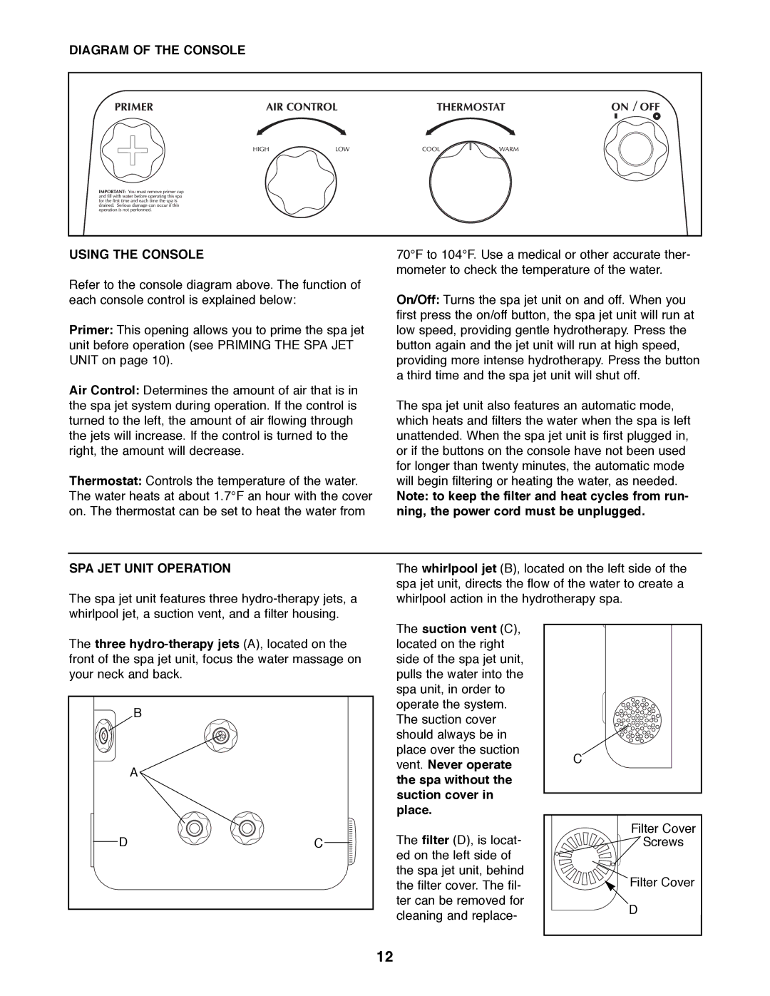
Refer to the console diagram above. The function of each console control is explained below:
Primer: This opening allows you to prime the spa jet unit before operation (see PRIMING THE SPA JET UNIT on page 10).
Air Control: Determines the amount of air that is in the spa jet system during operation. If the control is turned to the left, the amount of air flowing through the jets will increase. If the control is turned to the right, the amount will decrease.
Thermostat: Controls the temperature of the water. The water heats at about 1.7¡F an hour with the cover on. The thermostat can be set to heat the water from
70¡F to 104¡F. Use a medical or other accurate ther- mometer to check the temperature of the water.
On/Off: Turns the spa jet unit on and off. When you first press the on/off button, the spa jet unit will run at low speed, providing gentle hydrotherapy. Press the button again and the jet unit will run at high speed, providing more intense hydrotherapy. Press the button a third time and the spa jet unit will shut off.
The spa jet unit also features an automatic mode, which heats and filters the water when the spa is left unattended. When the spa jet unit is first plugged in, or if the buttons on the console have not been used for longer than twenty minutes, the automatic mode will begin filtering or heating the water, as needed.
Note: to keep the filter and heat cycles from run- ning, the power cord must be unplugged.
SPA JET UNIT OPERATION
The spa jet unit features three
The whirlpool jet (B), located on the left side of the spa jet unit, directs the flow of the water to create a whirlpool action in the hydrotherapy spa.
The three
| B |
| A |
D | C |
The suction vent (C), located on the right side of the spa jet unit, pulls the water into the spa unit, in order to operate the system. The suction cover should always be in place over the suction vent. Never operate the spa without the suction cover in place.
The filter (D), is locat- ed on the left side of the spa jet unit, behind the filter cover. The fil- ter can be removed for cleaning and replace-
C
Filter Cover
Screws
Filter Cover
D
12