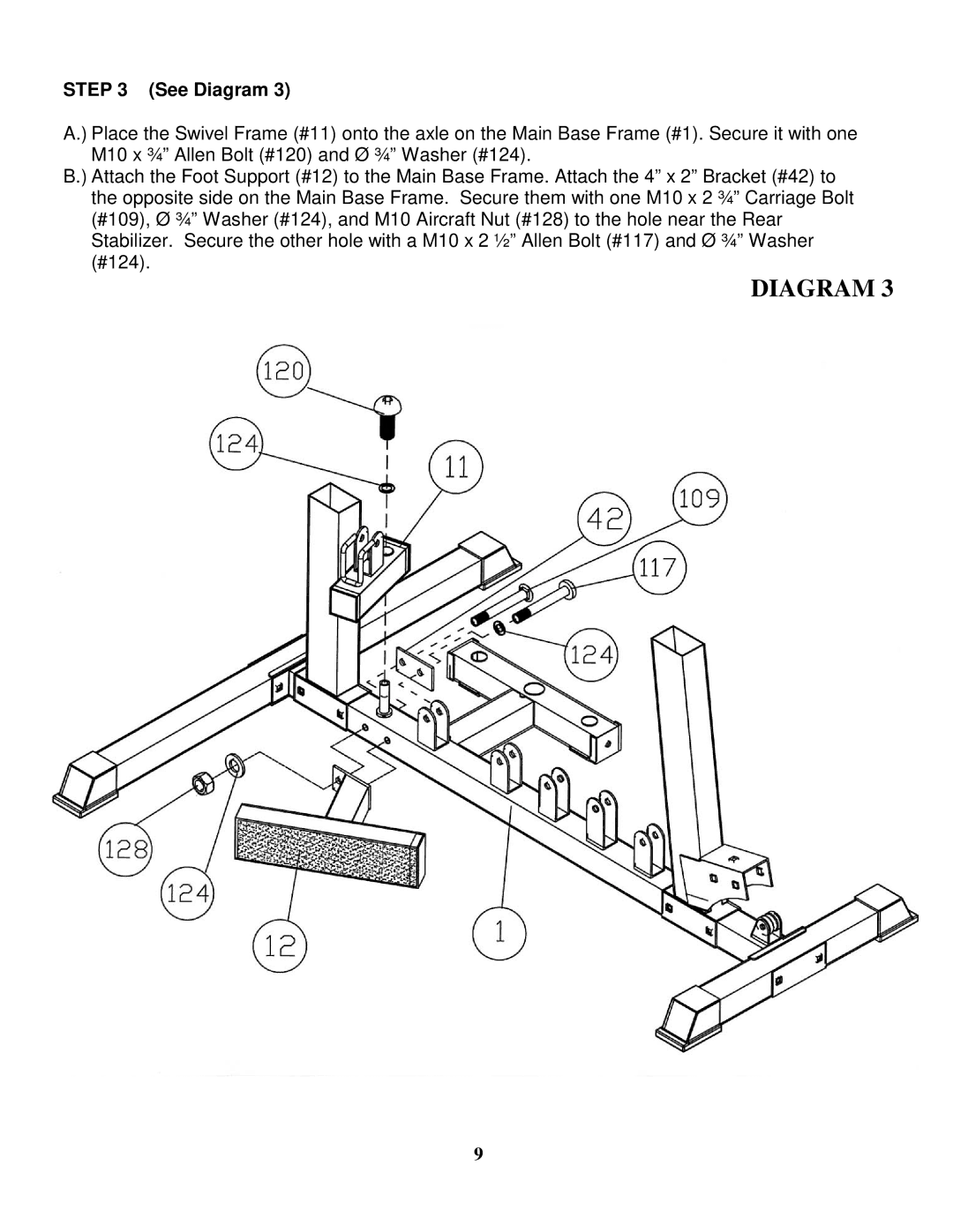
STEP 3 (See Diagram 3)
A.) Place the Swivel Frame (#11) onto the axle on the Main Base Frame (#1). Secure it with one M10 x ¾” Allen Bolt (#120) and Ø ¾” Washer (#124).
B.) Attach the Foot Support (#12) to the Main Base Frame. Attach the 4” x 2” Bracket (#42) to the opposite side on the Main Base Frame. Secure them with one M10 x 2 ¾” Carriage Bolt (#109), Ø ¾” Washer (#124), and M10 Aircraft Nut (#128) to the hole near the Rear Stabilizer. Secure the other hole with a M10 x 2 ½” Allen Bolt (#117) and Ø ¾” Washer (#124).
DIAGRAM 3
9