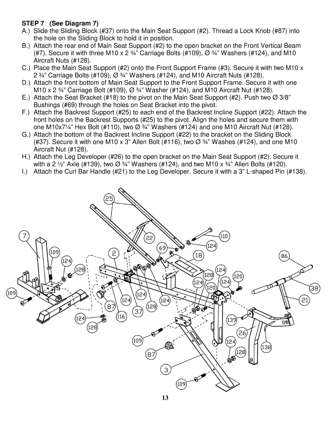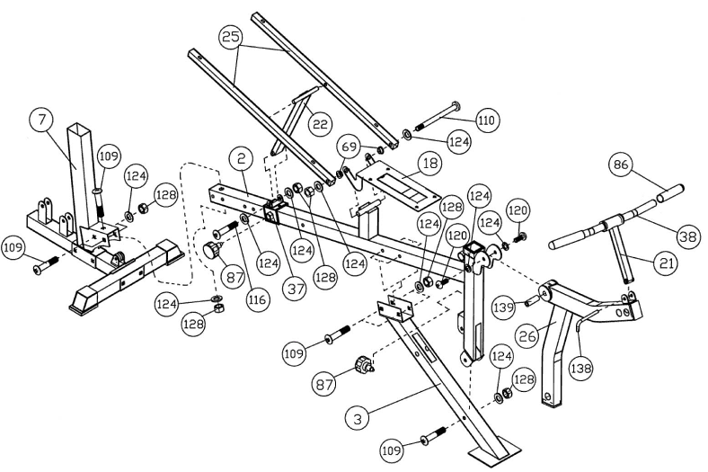
STEP 7 (See Diagram 7)
A.) Slide the Sliding Block (#37) onto the Main Seat Support (#2). Thread a Lock Knob (#87) into the hole on the Sliding Block to hold it in position.
B.) Attach the rear end of Main Seat Support (#2) to the open bracket on the Front Vertical Beam (#7). Secure it with three M10 x 2 ¾” Carriage Bolts (#109), Ø ¾” Washers (#124), and M10
Aircraft Nuts (#128).
C.) Place the Main Seat Support (#2) onto the Front Support Frame (#3). Secure it with two M10 x
2 ¾” Carriage Bolts (#109), Ø ¾” Washers (#124), and M10 Aircraft Nuts (#128).
D.) Attach the front bottom of Main Seat Support to the Front Support Frame. Secure it with one M10 x 2 ¾” Carriage Bolt (#109), Ø ¾” Washer (#124), and M10 Aircraft Nut (#128).
E.) Attach the Seat Bracket (#18) to the pivot on the Main Seat Support (#2). Push two Ø 3/8” Bushings (#69) through the holes on Seat Bracket into the pivot.
F.) Attach the Backrest Support (#25) to each end of the Backrest Incline Support (#22). Attach the front holes on the Backrest Supports (#25) to the pivot. Align the holes and secure them with one M10x7¼” Hex Bolt (#110), two Ø ¾” Washers (#124) and one M10 Aircraft Nut (#128).
G.) Attach the bottom of the Backrest Incline Support (#22) to the bracket on the Sliding Block (#37). Secure it with one M10 x 3” Allen Bolt (#116), two Ø ¾” Washes (#124), and one M10 Aircraft Nut (#128).
H.) Attach the Leg Developer (#26) to the open bracket on the Main Seat Support (#2). Secure it
with a 2 ½” Axle (#139), two Ø ¾” Washers (#124), and two M10 x ¾” Allen Bolts (#120).
I.) Attach the Curl Bar Handle (#21) to the Leg Developer. Secure it with a 3”
13