STEP 4 (See Diagram 4)
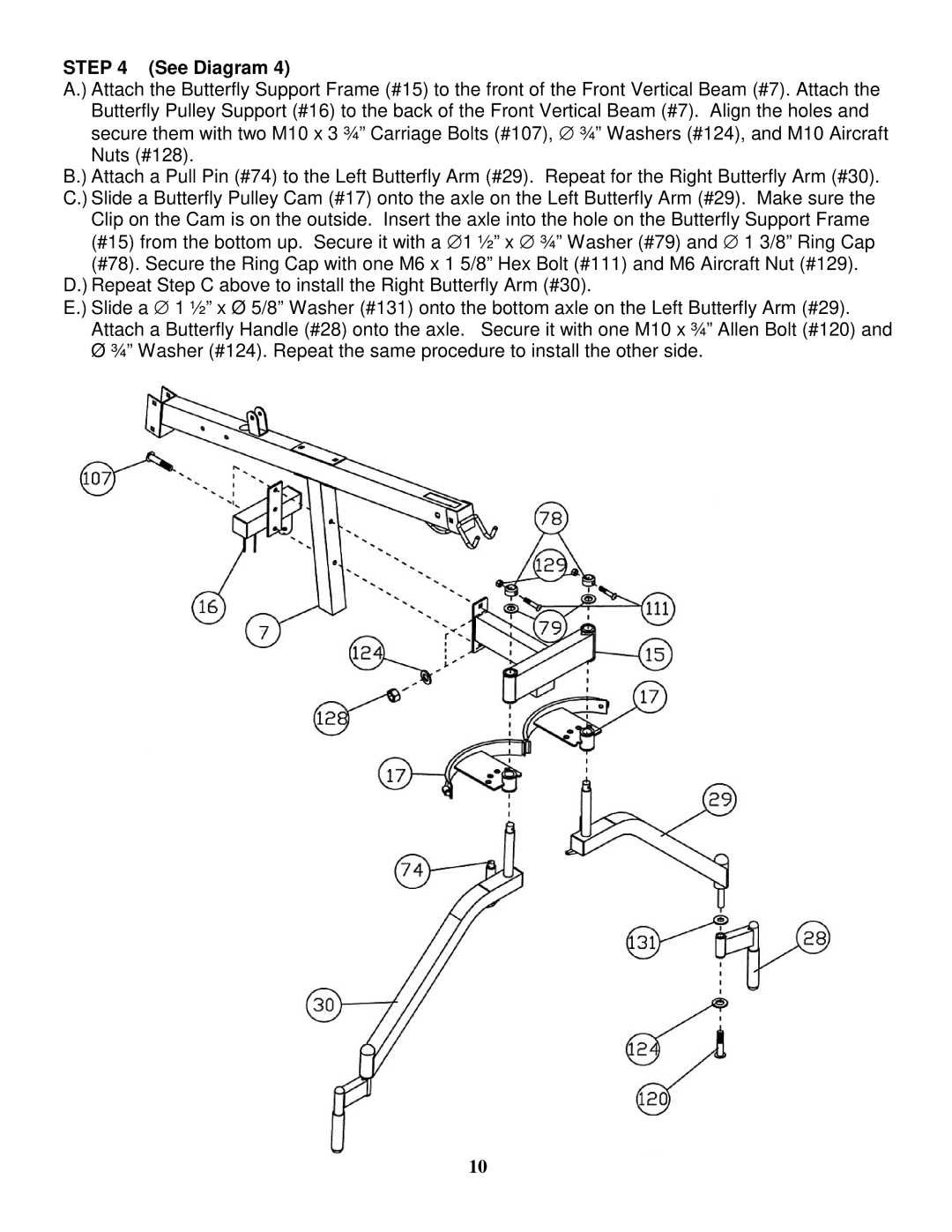
A.) Attach the Butterfly Support Frame (#15) to the front of the Front Vertical Beam (#7). Attach the Butterfly Pulley Support (#16) to the back of the Front Vertical Beam (#7). Align the holes and secure them with two M10 x 3 ¾” Carriage Bolts (#107), ∅ ¾” Washers (#124), and M10 Aircraft Nuts (#128).
B.) Attach a Pull Pin (#74) to the Left Butterfly Arm (#29). Repeat for the Right Butterfly Arm (#30). C.) Slide a Butterfly Pulley Cam (#17) onto the axle on the Left Butterfly Arm (#29). Make sure the Clip on the Cam is on the outside. Insert the axle into the hole on the Butterfly Support Frame (#15) from the bottom up. Secure it with a ∅ 1 ½” x ∅ ¾” Washer (#79) and ∅ 1 3/8” Ring Cap
(#78). Secure the Ring Cap with one M6 x 1 5/8” Hex Bolt (#111) and M6 Aircraft Nut (#129). D.) Repeat Step C above to install the Right Butterfly Arm (#30).
E.) Slide a ∅ 1 ½” x Ø 5/8” Washer (#131) onto the bottom axle on the Left Butterfly Arm (#29). Attach a Butterfly Handle (#28) onto the axle. Secure it with one M10 x ¾” Allen Bolt (#120) and Ø ¾” Washer (#124). Repeat the same procedure to install the other side.
10