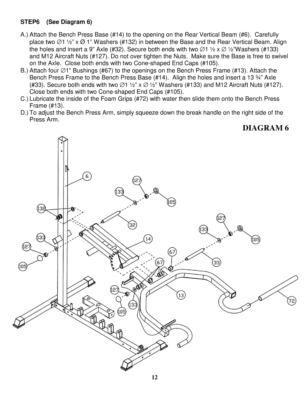
STEP6 (See Diagram 6)
A.) Attach the Bench Press Base (#14) to the opening on the Rear Vertical Beam (#6). Carefully place two ∅ 1 ½” x Ø 1” Washers (#132) in between the Base and the Rear Vertical Beam. Align the holes and insert a 9” Axle (#32). Secure both ends with two ∅ 1 ½ x ∅ ½”Washers (#133) and M12 Aircraft Nuts (#127). Do not over tighten the Nuts. Make sure the Base is free to swivel on the Axle. Close both ends with two
B.) Attach four ∅ 1” Bushings (#67) to the openings on the Bench Press Frame (#13). Attach the Bench Press Frame to the Bench Press Base (#14). Align the holes and insert a 13 ¾” Axle (#33). Secure both ends with two ∅ 1 ½” x ∅ ½” Washers (#133) and M12 Aircraft Nuts (#127). Close both ends with two
C.) Lubricate the inside of the Foam Grips (#72) with water then slide them onto the Bench Press Frame (#13).
D.) To adjust the Bench Press Arm, simply squeeze down the break handle on the right side of the Press Arm.
DIAGRAM 6
12
