STEP 2 (See Diagram 2)
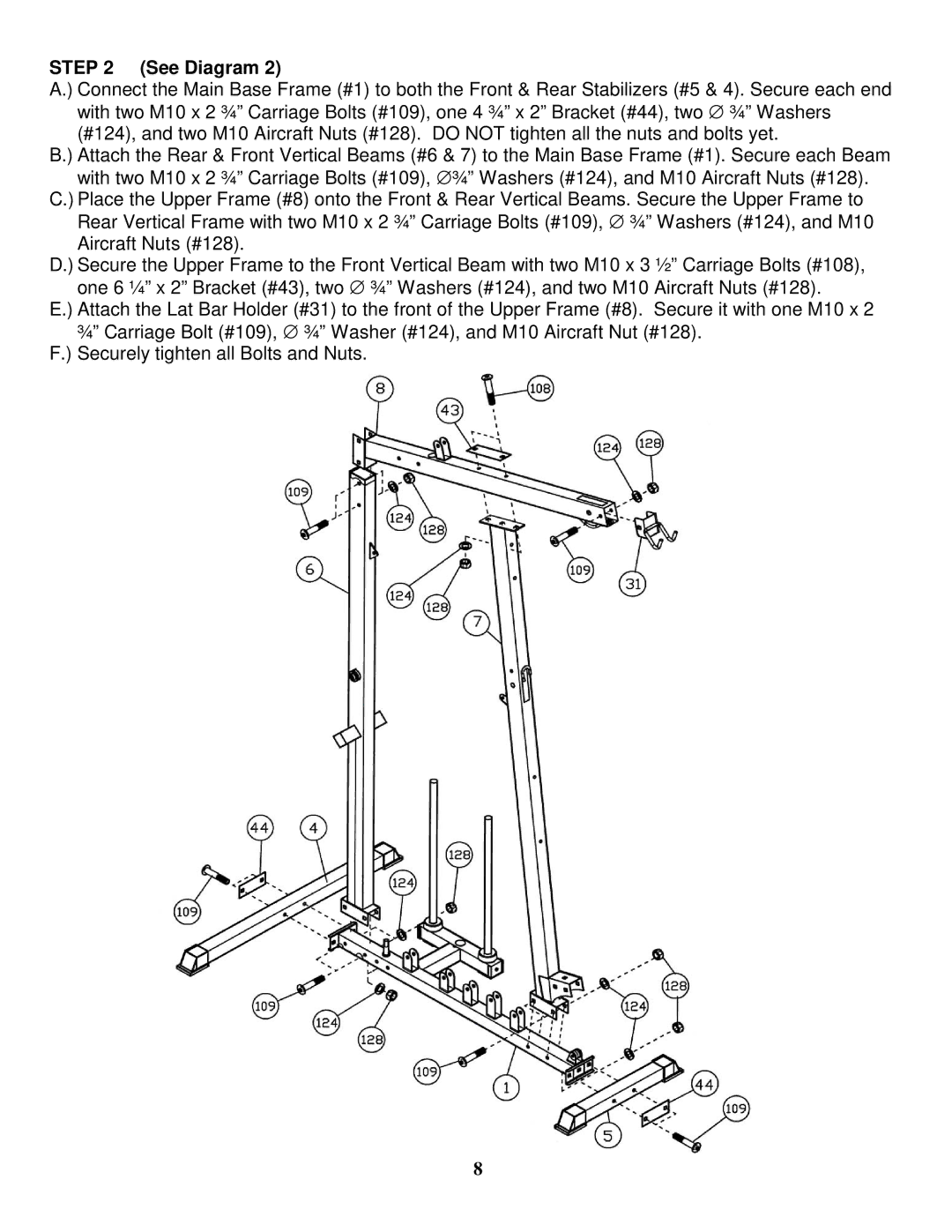
A.) Connect the Main Base Frame (#1) to both the Front & Rear Stabilizers (#5 & 4). Secure each end with two M10 x 2 ¾” Carriage Bolts (#109), one 4 ¾” x 2” Bracket (#44), two ∅ ¾” Washers (#124), and two M10 Aircraft Nuts (#128). DO NOT tighten all the nuts and bolts yet.
B.) Attach the Rear & Front Vertical Beams (#6 & 7) to the Main Base Frame (#1). Secure each Beam with two M10 x 2 ¾” Carriage Bolts (#109), ∅ ¾” Washers (#124), and M10 Aircraft Nuts (#128).
C.) Place the Upper Frame (#8) onto the Front & Rear Vertical Beams. Secure the Upper Frame to Rear Vertical Frame with two M10 x 2 ¾” Carriage Bolts (#109), ∅ ¾” Washers (#124), and M10 Aircraft Nuts (#128).
D.) Secure the Upper Frame to the Front Vertical Beam with two M10 x 3 ½” Carriage Bolts (#108), one 6 ¼” x 2” Bracket (#43), two ∅ ¾” Washers (#124), and two M10 Aircraft Nuts (#128).
E.) Attach the Lat Bar Holder (#31) to the front of the Upper Frame (#8). Secure it with one M10 x 2 ¾” Carriage Bolt (#109), ∅ ¾” Washer (#124), and M10 Aircraft Nut (#128).
F.) Securely tighten all Bolts and Nuts.
8