Studio system operation
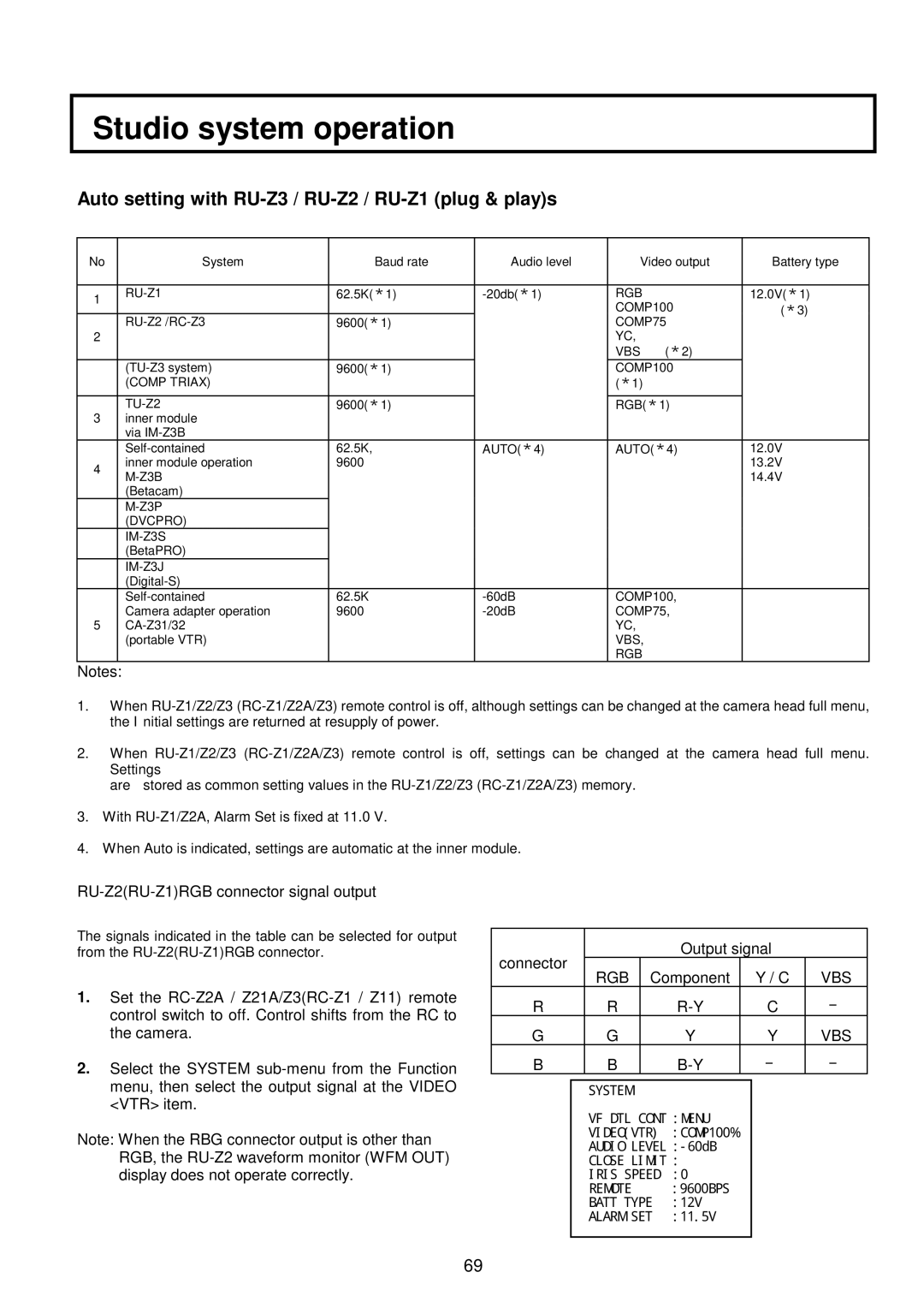
Auto setting with RU-Z3 / RU-Z2 / RU-Z1 (plug & play)s
No | System | Baud rate | Audio level | Video output | Battery type |
|
|
|
|
|
|
1 | 62.5K(*1) | RGB | 12.0V(*1) | ||
|
|
| COMP100 | (*3) | |
|
|
|
| ||
| 9600(*1) |
| COMP75 |
| |
2 |
|
|
| YC, |
|
|
|
|
| VBS (*2) |
|
| 9600(*1) |
| COMP100 |
| |
| (COMP TRIAX) |
|
| (*1) |
|
|
|
|
|
|
|
3 |
| 9600(*1) |
| RGB(*1) |
|
inner module |
|
|
|
| |
| via |
|
|
|
|
| 62.5K, | AUTO(*4) | AUTO(*4) | 12.0V | |
4 | inner module operation | 9600 |
|
| 13.2V |
|
|
| 14.4V | ||
|
|
|
| ||
| (Betacam) |
|
|
|
|
|
|
|
|
| |
| (DVCPRO) |
|
|
|
|
|
|
|
|
| |
| (BetaPRO) |
|
|
|
|
|
|
|
|
| |
|
|
|
|
| |
| 62.5K | COMP100, |
| ||
5 | Camera adapter operation | 9600 | COMP75, |
| |
|
| YC, |
| ||
| (portable VTR) |
|
| VBS, |
|
|
|
|
| RGB |
|
Notes:
1.When
2.When
are stored as common setting values in the
3.With
4.When Auto is indicated, settings are automatic at the inner module.
RU-Z2(RU-Z1)RGB connector signal output
The signals indicated in the table can be selected for output from the
1.Set the
2.Select the SYSTEM
Note: When the RBG connector output is other than RGB, the
connector |
|
| Output signal |
| |||
RGB | Component |
| Y / C | VBS | |||
|
|
| |||||
R | R |
|
| C | - | ||
G | G |
| Y |
| Y | VBS | |
B | B |
|
| - | - | ||
|
|
|
|
|
|
| |
|
| SYSTEM |
|
|
|
| |
|
| VF DTL CONT :MENU |
|
|
| ||
|
| VIDEO(VTR) | :COMP100% |
|
|
| |
|
| AUDIO |
|
|
| ||
|
| CLOSE LIMIT : |
|
|
| ||
|
| IRIS SPEED | :0 |
|
|
| |
|
| REMOTE | :9600BPS |
|
|
| |
|
| BATT TYPE | :12V |
|
|
| |
|
| ALARM SET | :11.5V |
|
|
| |
|
|
|
|
|
|
|
|
69