Facility names and functions
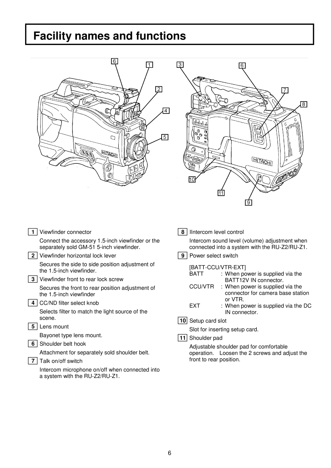
1Viewfinder connector
Connect the accessory
2Viewfinder horizontal lock lever
Secures the side to side position adjustment of the
3Viewfinder front to rear lock screw
Secures the front to rear position adjustment of the
4CC/ND filter select knob
Selects filter to match the light source of the scene.
5Lens mount
Bayonet type lens mount.
6Shoulder belt hook
Attachment for separately sold shoulder belt.
7Talk on/off switch
Intercom microphone on/off when connected into a system with the
8IIntercom level control
Intercom sound level (volume) adjustment when connected into a system with the
9Power select switch
[BATT-CCU/VTR-EXT]
BATT | : When power is supplied via the |
| BATT12V IN connector. |
CCU/VTR | : When power is supplied via the |
| connector for camera base station |
| or VTR. |
EXT | : When power is supplied via the DC |
| IN connector. |
10Setup card slot
Slot for inserting setup card.
11Shoulder pad
Adjustable shoulder pad for comfortable operation. Loosen the 2 screws and adjust the front to rear position.
6