General Disassembly

The following instructions provide the necessary information to disassemble, inspect, repair, and assemble the hoist. Parts drawings of the hoist assembly are provided in the parts section. If a hoist is being completely disassembled for any reason, follow the order of the topics as they are presented. It is recommended that all maintenance work on the hoist be performed on a bench.

In the process of disassembling the hoist, observe the following:

1.Never disassemble the hoist any further than is necessary to accomplish the needed repair. A good part can be damaged during the course of disassembly.

2.Never use excessive force when removing parts. Tapping gently around the perimeter of a cover or housing with a soft hammer, for example, is sufficient to break the seal.

3.Do not heat a part with a flame to free it for removal, unless the part being heated is already worn or damaged beyond repair and no additional damage will occur to other parts. In general, the hoist is designed to permit easy disassembly and assembly. The use of heat or excessive force should not be required.

4.Keep the work area as clean as practical, to prevent dirt and other foreign matter from getting into bearings or other moving parts.

5.When grasping a part in a vise, always use leather-covered or copper-covered vise jaws to protect the surface of the part and help prevent distortion. This is particularly true of threaded members, machined surfaces and housings.

6.Do not remove any part which is press fit in or on a subassembly unless the removal of that part is necessary for repairs or replacement.

Disassembly

Accessing Gear End

1.Remove the three nuts from gear cover.

2.Remove gear cover.

3.Remove nuts along with lockwashers from support plate .

4.Remove support plate, gears and bearings.

5.Remove retainer ring from load sheave and pry off gear.

Accessing Brake End

1.Remove the three nuts and screws from handwheel cover.

2.Remove handwheel cover.

3.Remove cotter pin and nut from pinion shaft.

4.Secure load sheave to prevent rotation and unscrew handwheel from pinion shaft. Handwheel is left hand (counterclockwise) threaded.

5.Remove brake discs and ratchet disc.

6.Secure load sheave to prevent rotation and unscrew brake hub from pinion shaft.

NOTICE

If ratchet pawls or springs are damaged or not functioning then remove retainer ring and replace damaged parts.

Slip Clutch Disassembly

1.Remove cotter pin and nut.

2.Pull handwheel/slip clutch assembly off of pinion shaft.

3.Remove nut from support and separate support, spring and single cone.

4.Remove screws and carefully pry double cone off of handwheel.

Accessing Load Sheave

Follow steps 1 through 5 in ‘Accessing Gear End’ and steps 1 through 6 in ‘Accessing Brake End’, then steps below.

1.Remove nuts and lockwashers from side plate.

2.Pull side plate away from studs in side plate.

3.Remove the top hook assembly, roller bearings, two-chain guides, chain stripper, and anchor hanger.

4.Lift load sheave from side plate. Being careful to catch roller bearings as they become free.

Bottom Hook Disassembly (2, 3 and 5 ton)

1.Remove three capscrews, lockwashers and nuts.

2.Separate plates and remove hook.

3.Lift out sheave assembly. Carefully slide idler sheave shaft from idler sheave and remove rollers.

Cleaning, Inspection and Repair

Use the following procedures to clean and inspect the components of the hoist.

Cleaning

Clean all hoist component parts in an acid free solvent (except for the brake disc). The use of a stiff bristle brush will facilitate the removal of accumulated dirt and sediments on the gears and frames. Dry each part using low pressure, filtered compressed air.

Inspection

All disassembled parts should be inspected to determine their fitness for continued use. Pay particular attention to the following:

1.Inspect all gears for worn, cracked, or broken teeth.

2.Inspect shafts for ridges caused by wear. If ridges caused by wear are apparent on shafts, replace the shaft.

3.Inspect all threaded items and replace those having damaged threads.

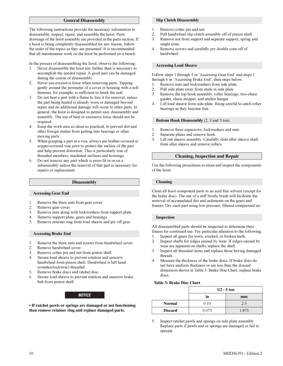
4.Measure the thickness of the brake discs. If brake discs do not have uniform thickness or are less than the discard dimension shown in Table 3: Brake Disc Chart, replace brake discs.

Table 3: Brake Disc Chart


1/2 - 5 ton


in


mm

Normal

0.10


2.5

Discard

0.075


1.875


5.Inspect ratchet pawls and springs on side plate assembly. Replace parts if pawls and or springs are damaged or fail to operate.

10

MHD56391 - Edition 2

Page 10
Image 10
Ingersoll-Rand SMB020, SMB050, SMB015, SMB030, SMB005, SMB010 manual General Disassembly, Cleaning, Inspection and Repair

SMB010, SMB020, SMB005, SMB030, SMB015 specifications

Ingersoll-Rand has a long-standing reputation for high-quality air compressors and associated products, featuring robust engineering and innovative technologies. Among their popular models are the SMB020, SMB005, SMB050, SMB015, and SMB030. Each model caters to a specific range of applications, making them versatile tools for various industries.

The SMB005 is ideal for small projects or businesses that require minimal compressed air. This model features a compact design, allowing it to fit into tight spaces without sacrificing performance. It boasts a low operating noise level, which is a critical factor for indoor applications. The SMB005 is equipped with a reliable motor and efficient air delivery, ensuring that it meets the demands of various pneumatic tools while maintaining energy efficiency.

Moving up the range, the SMB015 offers increased power and airflow, suitable for medium-sized applications. With advanced engineering, this model provides excellent reliability and performance. Its user-friendly interface allows for easy operation and monitoring. The SMB015’s built-in thermal protection prevents overheating, adding an additional layer of safety and longevity to the compressor.

The SMB020 model caters to slightly larger applications, providing enhanced airflow and pressure capabilities. This model has been designed with advanced noise-reduction technology, delivering a quieter operation while ensuring that it performs optimally. Its durable construction allows it to endure rigorous working conditions, making it a hit among professionals in construction, automotive, and manufacturing sectors.

For those seeking higher performance, the SMB030 and SMB050 models are standout choices. The SMB030 is engineered for heavy-duty applications, featuring high efficiency and reliability. With an advanced control system, it manages energy consumption effectively while ensuring maximum output. This model integrates modern technologies such as Variable Speed Drive (VSD), which adjusts the compressor's speed according to the air demand, thus optimizing energy usage and reducing overall costs.

Lastly, the SMB050 is the most powerful model in this series, designed for demanding tasks. It comes with advanced monitoring systems that allow users to track performance metrics in real-time. The robust cooling system ensures consistent operation, even under heavy loads. Its ease of maintenance and serviceability makes it a preferred choice for facilities that rely on consistent uptime.

In conclusion, the Ingersoll-Rand SMB series, including the SMB005, SMB015, SMB020, SMB030, and SMB050, demonstrates a blend of cutting-edge technologies, user-friendly design, and versatility. Each model caters to specific needs, providing reliable performance across various applications and industries.