4.8 Display assembly | 4 Replacement Procedures |
4.8Display assembly
Removing the display assembly
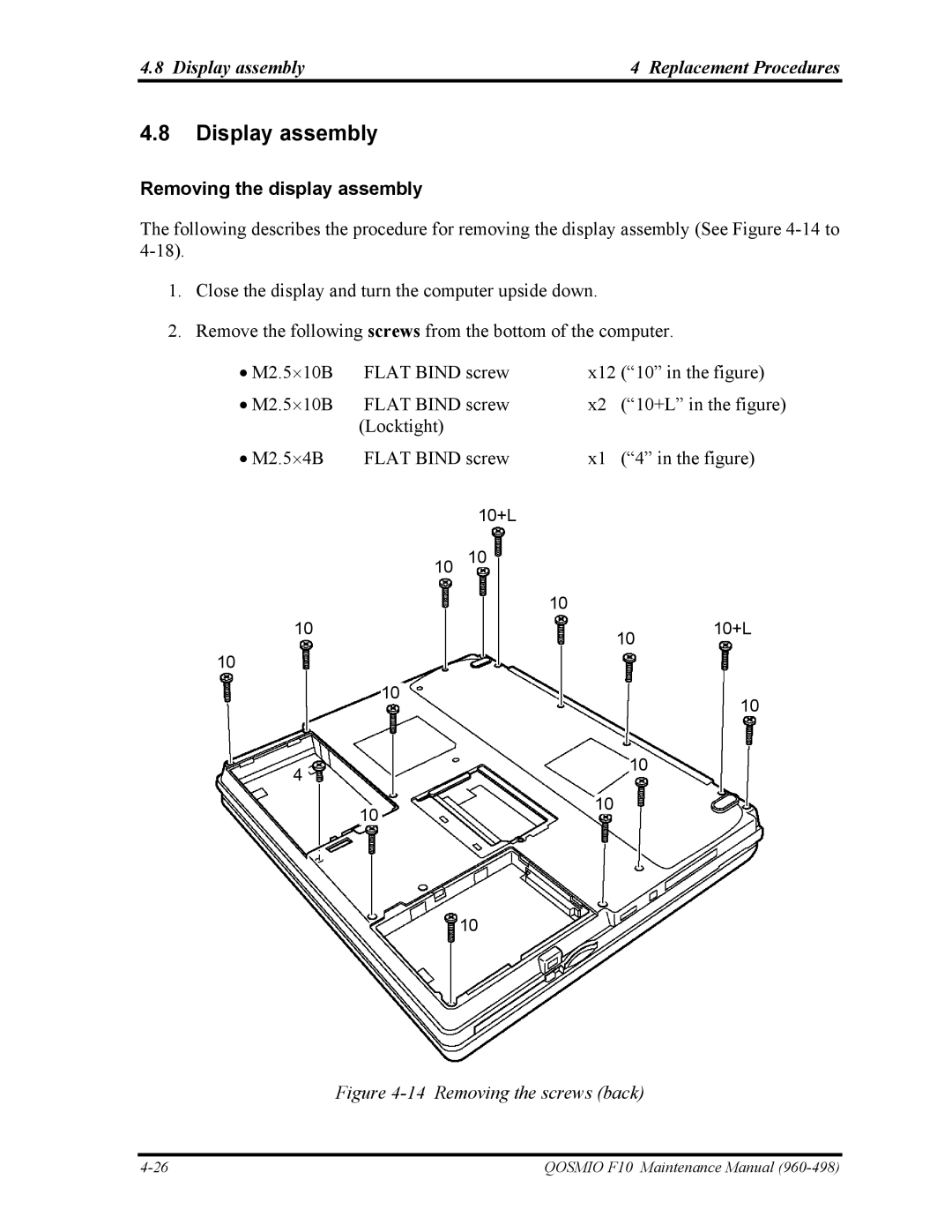
The following describes the procedure for removing the display assembly (See Figure
1.Close the display and turn the computer upside down.
2.Remove the following screws from the bottom of the computer.
• M2.5⋅10B | FLAT BIND screw |
| x12 (“10” in the figure) | ||||||||||
• M2.5⋅10B | FLAT BIND screw |
| x2 | (“10+L” in the figure) | |||||||||
|
|
| (Locktight) |
|
|
|
|
|
|
|
| ||
• M2.5⋅4B | FLAT BIND screw |
| x1 | (“4” in the figure) | |||||||||
|
|
|
|
|
| 10+L |
|
|
|
|
|
| |
|
|
|
|
|
|
|
|
|
|
|
|
|
|
|
|
|
|
|
| 10 |
|
|
|
|
|
|
|
|
|
| 10 |
|
|
|
|
|
|
|
| ||
|
|
|
|
|
|
|
|
|
|
| |||
|
|
|
|
|
|
|
|
|
|
|
|
|
|
|
|
|
|
|
|
|
| 10 |
|
|
|
|
|
|
|
|
|
|
|
|
|
|
|
|
|
|
|
10 |
|
|
|
|
|
|
|
|
| 10+L | |||
|
|
|
|
|
|
| 10 | ||||||
|
|
|
|
|
|
|
|
|
|
|
|
| |
10
|
|
| 10 |
|
|
|
|
|
| |
|
|
|
|
|
|
|
| 10 | ||
|
|
|
|
|
|
|
|
|
| |
|
|
|
|
|
|
|
|
|
|
|
|
|
|
|
| 10 |
|
| |||
4 |
|
|
|
|
|
|
|
|
| |
|
|
|
|
|
|
|
|
|
| |
|
|
|
|
|
|
|
|
|
|
|
|
|
|
|
| 10 |
|
|
|
| |
|
| 10 |
|
|
|
|
|
|
| |
|
|
|
|
|
|
|
|
|
| |
10
Figure 4-14 Removing the screws (back)
QOSMIO F10 Maintenance Manual |
