Chapter 2 Connecting Peripherals
2.1 Introduction
You can access most of the connectors from the top of the board while it is installed in the chassis. If you have a number of cards installed or have a packed chassis, you may need to partially remove the card to make all the connections.
2.2Primary (CN1) and Secondary (CN2) IDE Connec-
tors
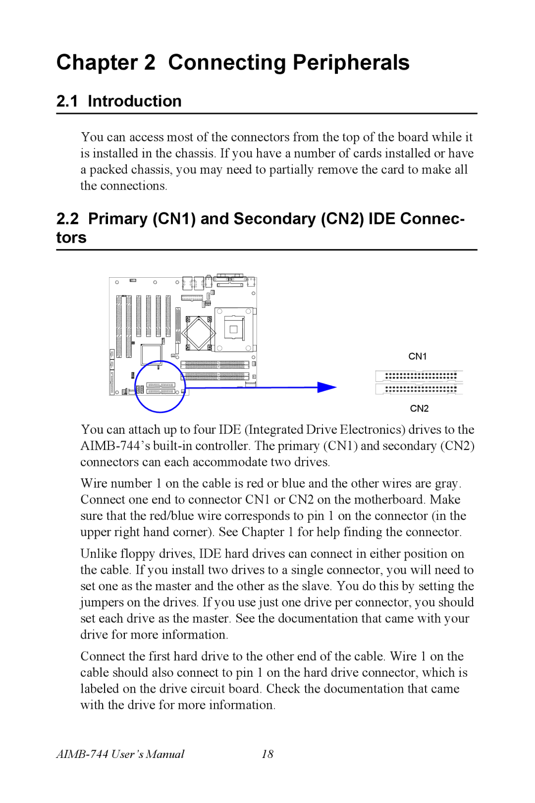
CN1
CN2
You can attach up to four IDE (Integrated Drive Electronics) drives to the
Wire number 1 on the cable is red or blue and the other wires are gray. Connect one end to connector CN1 or CN2 on the motherboard. Make sure that the red/blue wire corresponds to pin 1 on the connector (in the upper right hand corner). See Chapter 1 for help finding the connector.
Unlike floppy drives, IDE hard drives can connect in either position on the cable. If you install two drives to a single connector, you will need to set one as the master and the other as the slave. You do this by setting the jumpers on the drives. If you use just one drive per connector, you should set each drive as the master. See the documentation that came with your drive for more information.
Connect the first hard drive to the other end of the cable. Wire 1 on the cable should also connect to pin 1 on the hard drive connector, which is labeled on the drive circuit board. Check the documentation that came with the drive for more information.
18 |