1.5 Board Layout: Jumper and Connector Locations
CN13 | CN22 |
| J2 |
CN18 | CN29 |
|
|
CN21 | CN19 | CN17 | CN16 |
|
|
|
|
|
|
| CN 9 | CN38 |
| CN59 |
|
|
|
|
|
| CN11 |
|
|
|
|
|
|
| CN4 | |
|
|
|
|
| CN32 | CN31 |
| |
|
|
|
|
| CN55 |
| ||
PCI4 | PCI3 | PCI2 | PCI1 |
| CN15 |
| ||
|
|
| ||||||
J8 |
|
|
|
|
|
| CN57 |
|
|
|
|
|
| ATX2 |
| ATX1 |
|
|
|
|
|
| AGP1 | CN56 |
| |
|
|
|
|
|
|
| ||
| J5 |
|
|
| CN6 |
|
|
|
|
|
|
|
|
|
|
| |
CN23 | J56 |
|
|
|
|
|
|
|
|
|
|
|
|
|
|
| |
|
|
|
|
| J7 |
|
|
|
CN10 |
|
|
|
| DIMM1 |
|
| CN14 |
|
|
|
|
|
|
| ||
|
|
|
|
|
|
|
| |
|
|
|
| J1 | DIMM2 |
|
|
|
CN3 |
|
|
|
| DIMM3 |
|
| CN64 |
|
|
|
|
|
|
| ||
|
|
|
|
|
|
|
| |
|
|
|
|
| DIMM4 |
|
| CN62 |
| SA0 SA1 |
|
| CN2 |
|
| ||
|
|
|
|
|
| |||
| CN12 |
|
|
| CN1 CN37 |
|
|
|
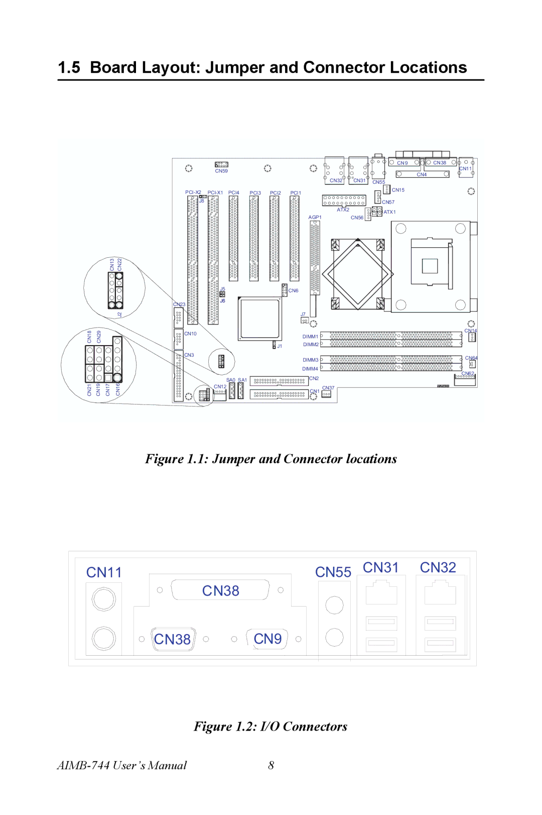
Figure 1.1: Jumper and Connector locations
CN11 | CN55 | CN31 | CN32 |
| CN38 |
|
|
CN38 CN9
Figure 1.2: I/O Connectors
8 |
