Module Components
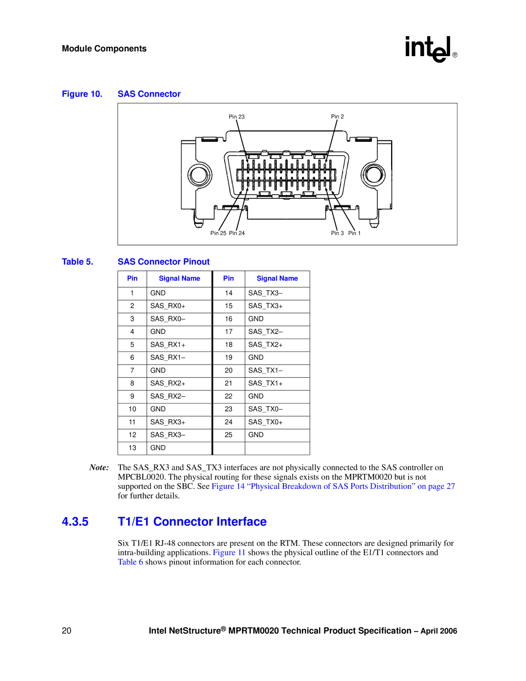
Figure 10. SAS Connector
Pin 23 |
|
|
|
|
|
|
|
|
|
| Pin 2 | ||||||||||||||||||||
|
|
|
|
|
|
|
|
|
|
|
|
|
|
|
|
|
|
|
|
|
|
|
|
|
|
|
|
|
|
|
|
|
|
|
|
|
|
|
|
|
|
|
|
|
|
|
|
|
|
|
|
|
|
|
|
|
|
|
|
|
|
|
|
|
|
|
|
|
|
|
|
|
|
|
|
|
|
|
|
|
|
|
|
|
|
|
|
|
|
|
|
|
|
|
|
|
|
|
|
|
|
|
|
|
|
|
|
|
|
|
|
|
|
|
|
|
|
|
|
|
|
|
|
|
|
|
|
|
|
|
|
|
|
|
|
|
|
|
|
|
|
|
|
|
|
|
|
|
|
|
|
|
|
|
|
|
|
|
|
|
|
|
|
|
|
|
|
|
|
|
|
|
|
|
|
|
|
|
|
|
|
|
|
|
|
|
|
|
|
|
|
|
|
|
|
|
|
|
|
|
|
|
|
|
|
|
|
|
|
|
|
|
|
|
|
|
|
|
|
|
|
|
|
|
|
|
|
|
|
|
|
|
|
|
|
|
|
|
|
|
|
|
|
|
|
|
|
|
|
|
|
|
|
|
|
|
|
|
|
|
|
|
|
|
|
|
|
|
|
|
|
|
|
|
|
|
|
|
|
|
|
|
|
|
|
|
|
|
|
|
|
|
|
|
|
|
|
|
|
|
|
|
|
|
|
|
|
|
|
|
|
|
|
|
|
|
|
|
|
|
|
|
|
|
|
|
|
|
|
|
|
|
|
|
|
|
|
|
|
|
|
|
|
|
|
|
|
|
|
|
|
|
|
| Pin 25 Pin 24 |
| Pin 3 Pin 1 | |
|
|
|
|
|
|
|
Table 5. | SAS Connector Pinout |
|
|
|
| |
|
|
|
|
|
|
|
| Pin | Signal Name |
| Pin | Signal Name |
|
|
|
|
|
|
|
|
| 1 | GND |
| 14 | SAS_TX3– |
|
|
|
|
|
|
|
|
| 2 | SAS_RX0+ |
| 15 | SAS_TX3+ |
|
|
|
|
|
|
|
|
| 3 | SAS_RX0– |
| 16 | GND |
|
|
|
|
|
|
|
|
| 4 | GND |
| 17 | SAS_TX2– |
|
|
|
|
|
|
|
|
| 5 | SAS_RX1+ |
| 18 | SAS_TX2+ |
|
|
|
|
|
|
|
|
| 6 | SAS_RX1– |
| 19 | GND |
|
|
|
|
|
|
|
|
| 7 | GND |
| 20 | SAS_TX1– |
|
|
|
|
|
|
|
|
| 8 | SAS_RX2+ |
| 21 | SAS_TX1+ |
|
|
|
|
|
|
|
|
| 9 | SAS_RX2– |
| 22 | GND |
|
|
|
|
|
|
|
|
| 10 | GND |
| 23 | SAS_TX0– |
|
|
|
|
|
|
|
|
| 11 | SAS_RX3+ |
| 24 | SAS_TX0+ |
|
|
|
|
|
|
|
|
| 12 | SAS_RX3– |
| 25 | GND |
|
|
|
|
|
|
|
|
| 13 | GND |
|
|
|
|
|
|
|
|
|
|
|
Note: The SAS_RX3 and SAS_TX3 interfaces are not physically connected to the SAS controller on MPCBL0020. The physical routing for these signals exists on the MPRTM0020 but is not supported on the SBC. See Figure 14 “Physical Breakdown of SAS Ports Distribution” on page 27 for further details.
4.3.5T1/E1 Connector Interface
Six T1/E1
20 | Intel NetStructure® MPRTM0020 Technical Product Specification – April 2006 |
