Module Components
4.3.7Zone 3 Rear Transition Module Data/Control Connectors
The MPRTM0020 implementation includes three data connectors (P31, P32, P33) that mate directly to the MPCBL0020 Single Board Computer without connecting through the backplane. Each Zone 3 data/control connection consists of
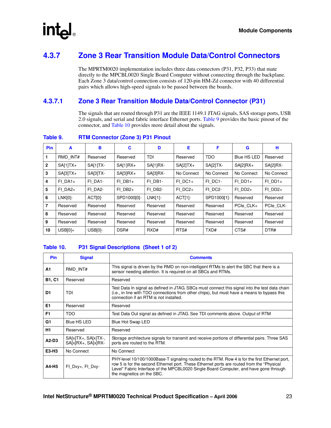
4.3.7.1Zone 3 Rear Transition Module Data/Control Connector (P31)
The signals that are routed through P31 are the IEEE 1149.1 JTAG signals, SAS storage ports, USB
2.0signals, and serial and fabric interface Ethernet ports. Table 9 provides the basic pinout of the connector, and Table 10 provides more detail about the signals.
Table 9. | RTM Connector (Zone 3) P31 Pinout |
|
|
|
| ||||
|
|
|
|
|
|
|
|
|
|
Pin | A |
| B | C | D | E | F | G | H |
|
|
|
|
|
|
|
|
| |
1 | RMD_INT# | Reserved | Reserved | TDI | Reserved | TDO | Blue HS LED | Reserved | |
|
|
|
|
|
|
|
|
|
|
2 | SA[1]TX+ |
| SA[1]TX- | SA[1]RX+ | SA[1]RX- | SA[2]TX+ | SA[2]TX- | SA[2]RX+ | SA[2]RX- |
|
|
|
|
|
|
|
|
|
|
3 | SA[3]TX+ |
| SA[3]TX- | SA[3]RX+ | SA[3]RX- | No Connect | No Connect | No Connect | No Connect |
|
|
|
|
|
|
|
|
|
|
4 | FI_DA1+ |
| FI_DA1- | FI_DB1+ | FI_DB1- | FI_DC1+ | FI_DC1- | FI_DD1+ | FI_DD1+ |
|
|
|
|
|
|
|
|
|
|
5 | FI_DA2+ |
| FI_DA2- | FI_DB2+ | FI_DB2- | FI_DC2+ | FI_DC2- | FI_DD2+ | FI_DD2+ |
|
|
|
|
|
|
|
|
|
|
6 | LNK[0]- |
| ACT[0]- | SPD1000[0]- | LNK[1]- | ACT[1]- | SPD1000[1]- | Reserved | Reserved |
|
|
|
|
|
|
|
|
|
|
7 | Reserved |
| Reserved | Reserved | Reserved | Reserved | Reserved | PCIe_CLK+ | PCIe_CLK- |
|
|
|
|
|
|
|
|
|
|
8 | Reserved |
| Reserved | Reserved | Reserved | Reserved | Reserved | Reserved | Reserved |
|
|
|
|
|
|
|
|
|
|
9 | Reserved |
| Reserved | Reserved | Reserved | Reserved | Reserved | Reserved | Reserved |
|
|
|
|
|
|
|
|
|
|
10 | USB[0]+ |
| USB[0]- | DSR# | RXD# | RTS# | TXD# | CTS# | DTR# |
|
|
|
|
|
|
|
|
|
|
Table 10. | P31 Signal Descriptions (Sheet 1 of 2) | |||
|
|
|
| |
Pin |
| Signal | Comments | |
|
|
|
| |
A1 | RMD_INT# | This signal is driven by the RMD on | ||
sensor needing attention. It is required on all SBCs and RTMs. | ||||
|
|
| ||
|
|
| ||
B1, C1 | Reserved | Reserved | ||
|
|
|
| |
|
|
| Test Data In signal as defined in JTAG. SBCs must connect this signal into the test data chain | |
D1 | TDI |
| (i.e., in line with TDO connections from other chips), but must have a means to bypass this | |
|
|
| connection if an RTM is not installed. | |
|
|
| ||
E1 | Reserved | Reserved | ||
|
|
|
| |
F1 | TDO |
| Test Data Out signal as defined in JTAG. See TDI comments above. Output of RTM | |
|
|
| ||
G1 | Blue HS LED | Blue Hot Swap LED | ||
|
|
| ||
H1 | Reserved | Reserved | ||
|
|
| ||
| SA[x]TX+, | Storage architecture signals for transmit and receive portions of differential pairs. Three SAS | ||
SA[x]RX+, SA[x]RX- | ports are routed to the RTM. | |||
| ||||
|
|
| ||
| No Connect | No Connect | ||
|
|
|
| |
|
|
| ||
| FI_Dxy+, FI_Dxy- | row 5 is for the second Ethernet port. These Ethernet ports are routed from the “Physical | ||
Level” Fabric Interface of the MPCBL0020 Single Board Computer, and have gone through | ||||
|
|
| ||
|
|
| the magnetics on the SBC. | |
|
|
|
| |
Intel NetStructure® MPRTM0020 Technical Product Specification – April 2006 | 23 |