Module Components
Table 13. GPIO Signal Mapping (Sheet 2 of 2)
GPIO Signals | Pin on ADM1026 |
|
|
Health Red LED Control | 9 |
|
|
USB_OC Monitor | 12 |
|
|
Payload Power Enable | 2 |
|
|
Payload PowerGood | 43 |
|
|
4.3.10Power Supplies
The MPRTM0020 RTM needs several voltages that are not available from the SBC. The P30 connection to the SBC only provides two power supplies:
•+12 V voltage rail (420 mA maximum current) is used as the main input voltage for the RTM
•+3.3 V SUS voltage powers the management circuitry on the RTM (ADM1026, I2C pullup, etc.)
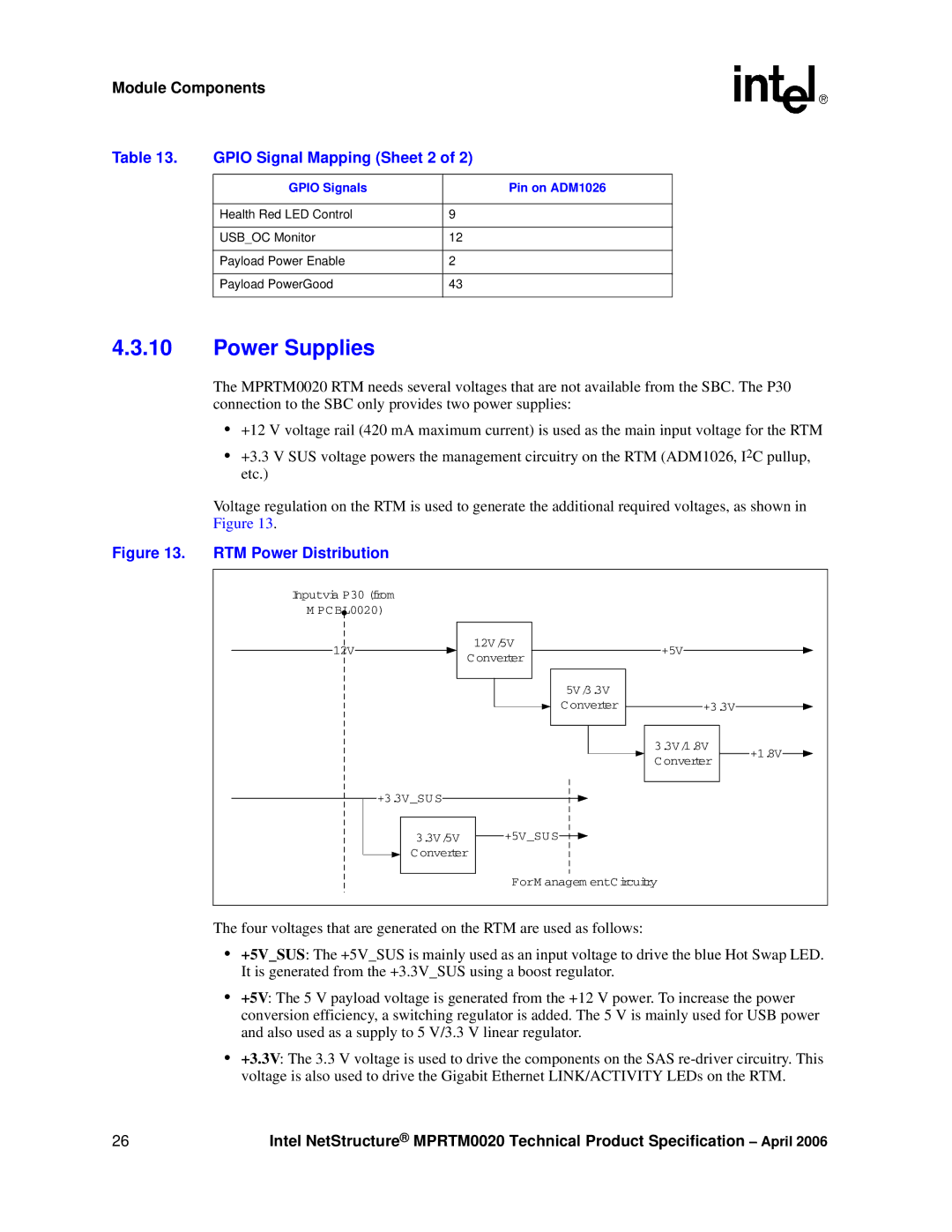
Voltage regulation on the RTM is used to generate the additional required voltages, as shown in Figure 13.
Figure 13. RTM Power Distribution
Inputvia P30 (from |
|
| |
M PCBL0020) |
|
| |
12V | 12V/5V | +5V | |
Converter | |||
|
| ||
| 5V/3.3V |
| |
| Converter | +3.3V | |
|
| 3.3V/1.8V | |
|
| +1.8V | |
|
| Converter | |
+3.3V_SU S |
|
| |
3.3V/5V | +5V_SUS |
| |
Converter |
| ||
| ForM anagem entCircuitry | ||
The four voltages that are generated on the RTM are used as follows:
•+5V_SUS: The +5V_SUS is mainly used as an input voltage to drive the blue Hot Swap LED. It is generated from the +3.3V_SUS using a boost regulator.
•+5V: The 5 V payload voltage is generated from the +12 V power. To increase the power conversion efficiency, a switching regulator is added. The 5 V is mainly used for USB power and also used as a supply to 5 V/3.3 V linear regulator.
•+3.3V: The 3.3 V voltage is used to drive the components on the SAS
26 | Intel NetStructure® MPRTM0020 Technical Product Specification – April 2006 |