3 Maintaining Your Server
Replacing the USB Cable
1.Remove the left access cover.
2.Remove the bezel.
3.Disconnect the existing USB cable from the server board.
4.Disconnect the bracket the attaches the USB cable to the front of the chassis.
5.Remove all
✏NOTE
When removing a
6.Push down on the latches for the
7.Tip the retention bracket slightly forward to create a gap between the top of the device and the chassis frame.
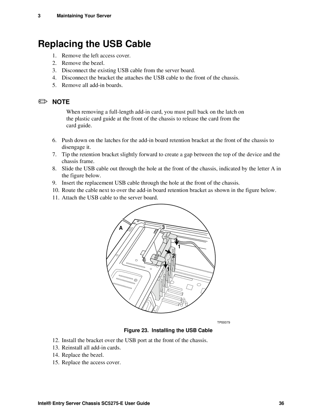
8.Slide the USB cable out through the hole at the front of the chassis, indicated by the letter A in the figure below.
9.Insert the replacement USB cable through the hole at the front of the chassis.
10.Route the cable next to over the
11.Attach the USB cable to the server board.
A3
1
2
1 ![]()
![]()
TP00079
Figure 23. Installing the USB Cable
12.Install the bracket over the USB port at the front of the chassis.
13.Reinstall all
14.Replace the bezel.
15.Replace the access cover.
Intel® Entry Server Chassis | 36 |