SECTION
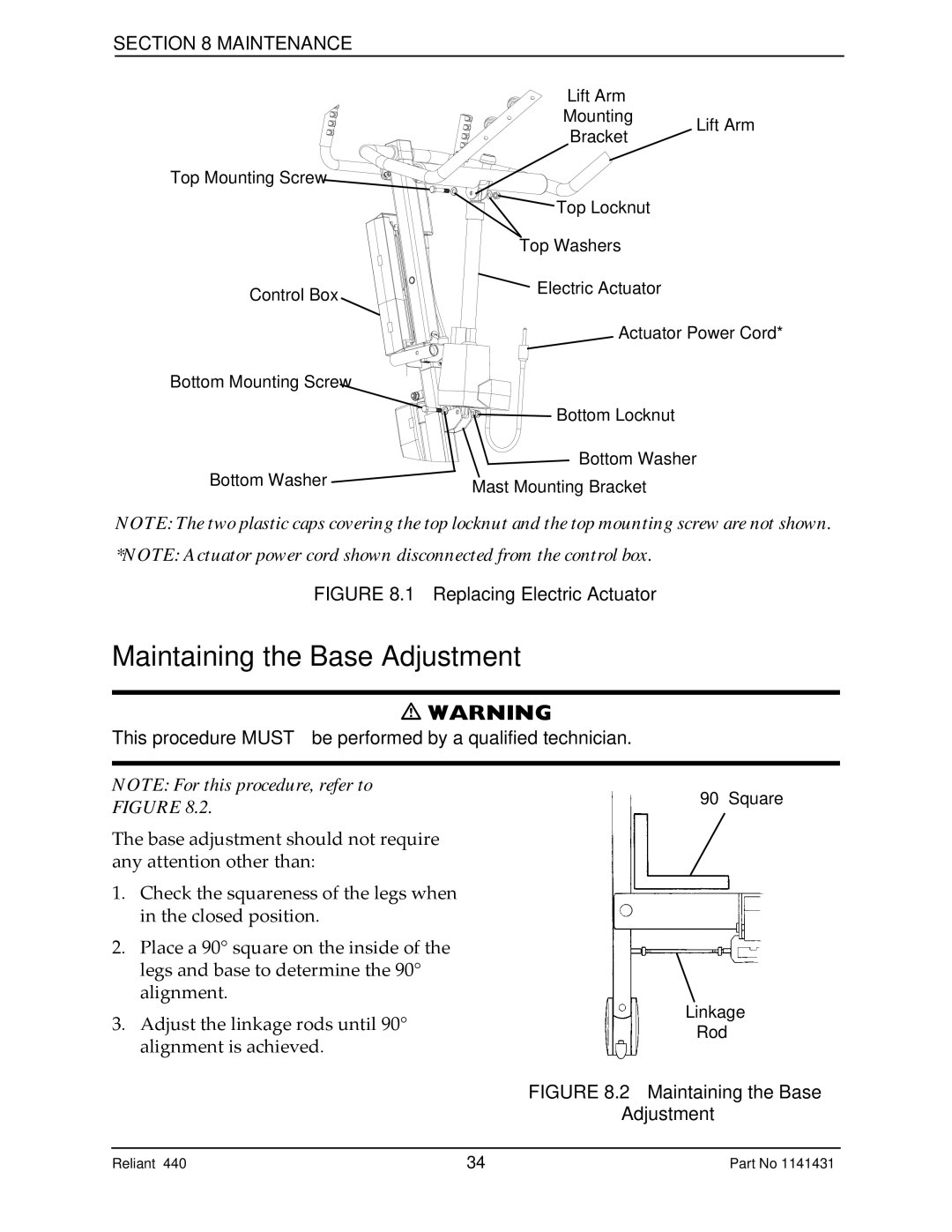
Lift Arm
Mounting Lift Arm
Bracket
Top Mounting Screw
| Top Locknut |
| Top Washers |
Control Box | Electric Actuator |
|
Actuator Power Cord*
Bottom Mounting Screw
Bottom Locknut
Bottom Washer
Bottom Washer ![]()
![]() Mast Mounting Bracket
Mast Mounting Bracket
NOTE: The two plastic caps covering the top locknut and the top mounting screw are not shown.
*NOTE: Actuator power cord shown disconnected from the control box.
FIGURE 8.1 Replacing Electric Actuator
Maintaining the Base Adjustment
WARNING
This procedure MUST be performed by a qualified technician.
NOTE: For this procedure, refer to FIGURE 8.2.
The base adjustment should not require any attention other than:
1.Check the squareness of the legs when in the closed position.
2.Place a 90° square on the inside of the legs and base to determine the 90° alignment.
3.Adjust the linkage rods until 90° alignment is achieved.
Reliant™ 440 | 34 | Part No 1141431 |