SECTION 6: PARTS SECTION
CYCLE COUNTER RETROFIT KIT
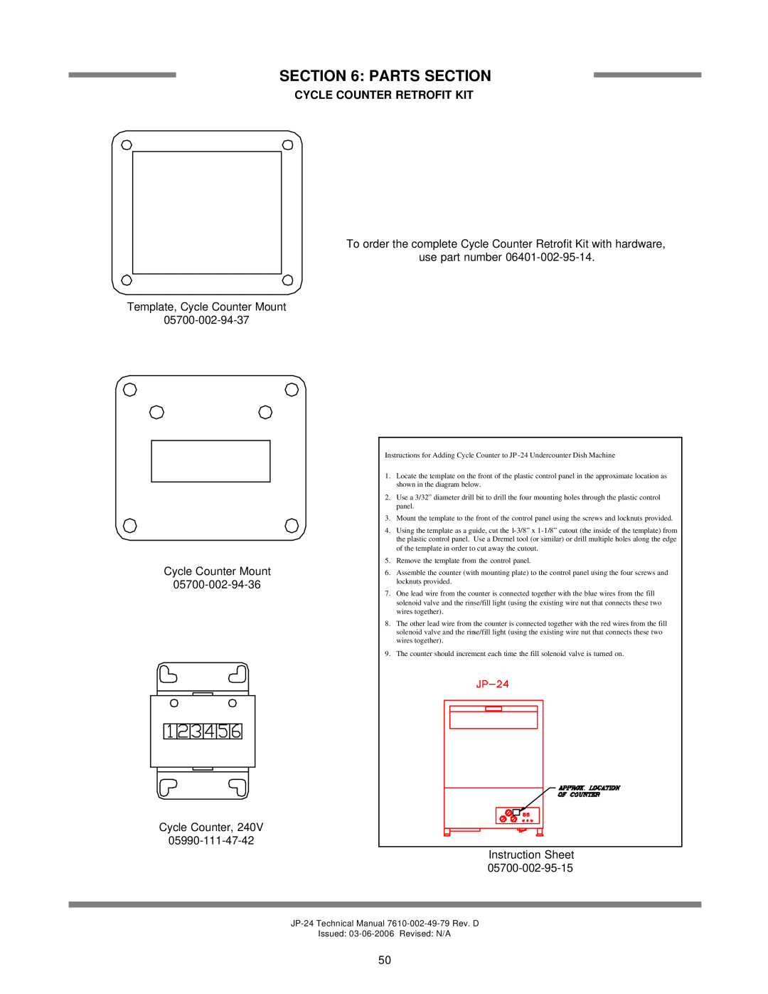
To order the complete Cycle Counter Retrofit Kit with hardware,
use part number
Template, Cycle Counter Mount
Cycle Counter Mount
Instructions for Adding Cycle Counter to JP
1.Locate the template on the front of the plastic control panel in the approximate location as shown in the diagram below.
2.Use a 3/32” diameter drill bit to drill the four mounting holes through the plastic control panel.
3.Mount the template to the front of the control panel using the screws and locknuts provided.
4.Using the template as a guide, cut the
5.Remove the template from the control panel.
6.Assemble the counter (with mounting plate) to the control panel using the four screws and locknuts provided.
7.One lead wire from the counter is connected together with the blue wires from the fill solenoid valve and the rinse/fill light (using the existing wire nut that connects these two wires together).
8.The other lead wire from the counter is connected together with the red wires from the fill solenoid valve and the rinse/fill light (using the existing wire nut that connects these two wires together).
9.The counter should increment each time the fill solenoid valve is turned on.
Cycle Counter, 240V
Instruction Sheet
Issued:
50