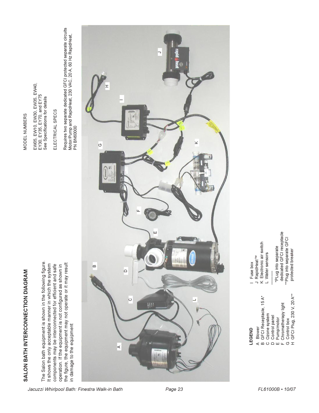
FL61000 specifications
The Jacuzzi FL61000 is an innovative and versatile hot tub that combines luxury with advanced technology to create an enjoyable and therapeutic experience. Designed for both relaxation and socialization, the FL61000 can accommodate up to six individuals, making it perfect for family gatherings or intimate get-togethers with friends.One of the standout features of the Jacuzzi FL61000 is its powerful hydrotherapy system. The hot tub is equipped with strategically placed jets that provide targeted massage to various muscle groups throughout the body. With a variety of jet types, including rotating and directional jets, users can customize their massage experience according to individual needs.
The FL61000 also boasts an advanced water management system, which enhances the quality and clarity of water. Equipped with a filtration system that uses enhanced sanitation technologies, including ozone purification, the hot tub minimizes chemical usage while ensuring clean and safe water. This gives users peace of mind while they indulge in relaxation.
In terms of design, the Jacuzzi FL61000 is aesthetically pleasing with its sleek, modern lines and available in several stylish colors that can complement any outdoor space. Its durable acrylic shell provides long-lasting beauty and is engineered to withstand various weather conditions. The hot tub is framed with a robust composite base, ensuring longevity and stability.
Energy efficiency is another hallmark of the FL61000. It features an insulating cover that reduces heat loss, ensuring that energy costs are kept low. The hot tub is also equipped with an energy-efficient pump that minimizes electricity consumption without compromising performance.
Additional technologies integrated into the Jacuzzi FL61000 enhance user convenience and enjoyment. The intuitive control panel allows for easy customization of temperature, jet speed, and lighting. Some models even support smart technology, offering remote access through mobile devices for added flexibility.
Finally, safety features such as non-slip surfaces and easy-access steps ensure that users can enjoy the hot tub with peace of mind. Whether seeking relief from everyday stress or looking to create a social hub at home, the Jacuzzi FL61000 delivers a luxurious experience that can be enjoyed year-round.

