Extension Cords
If an extension cord is necessary, make sure the cord rating is suitable for the amperage listed on the machine's motor plate. An undersize cord will cause a drop in line voltage resulting in loss of power and overheating.
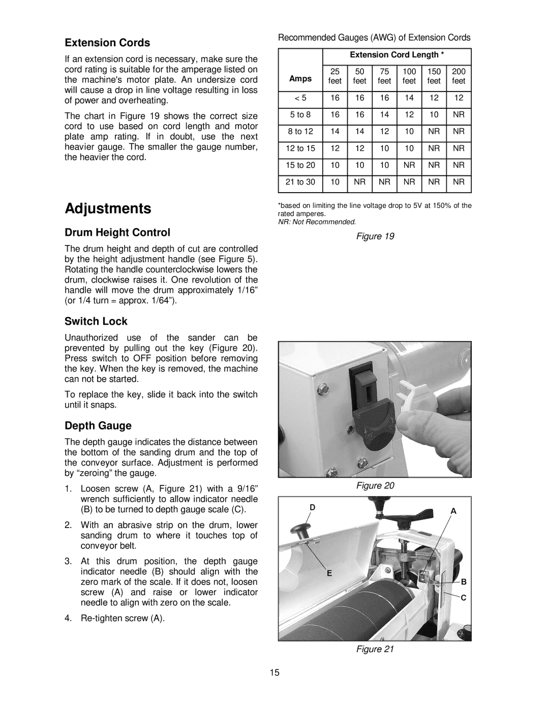
The chart in Figure 19 shows the correct size cord to use based on cord length and motor plate amp rating. If in doubt, use the next heavier gauge. The smaller the gauge number, the heavier the cord.
Adjustments
Drum Height Control
The drum height and depth of cut are controlled by the height adjustment handle (see Figure 5). Rotating the handle counterclockwise lowers the drum, clockwise raises it. One revolution of the handle will move the drum approximately 1/16” (or 1/4 turn = approx. 1/64”).
Recommended Gauges (AWG) of Extension Cords
|
| Extension Cord Length * |
| |||
|
|
|
|
|
|
|
Amps | 25 | 50 | 75 | 100 | 150 | 200 |
feet | feet | feet | feet | feet | feet | |
|
|
|
|
|
|
|
< 5 | 16 | 16 | 16 | 14 | 12 | 12 |
|
|
|
|
|
|
|
5 to 8 | 16 | 16 | 14 | 12 | 10 | NR |
|
|
|
|
|
|
|
8 to 12 | 14 | 14 | 12 | 10 | NR | NR |
|
|
|
|
|
|
|
12 to 15 | 12 | 12 | 10 | 10 | NR | NR |
|
|
|
|
|
|
|
15 to 20 | 10 | 10 | 10 | NR | NR | NR |
|
|
|
|
|
|
|
21 to 30 | 10 | NR | NR | NR | NR | NR |
|
|
|
|
|
|
|
*based on limiting the line voltage drop to 5V at 150% of the rated amperes.
NR: Not Recommended.
Figure 19
Switch Lock
Unauthorized use of the sander can be prevented by pulling out the key (Figure 20). Press switch to OFF position before removing the key. When the key is removed, the machine can not be started.
To replace the key, slide it back into the switch until it snaps.
Depth Gauge
The depth gauge indicates the distance between the bottom of the sanding drum and the top of the conveyor surface. Adjustment is performed by “zeroing” the gauge.
1.Loosen screw (A, Figure 21) with a 9/16” wrench sufficiently to allow indicator needle
(B) to be turned to depth gauge scale (C).
2.With an abrasive strip on the drum, lower sanding drum to where it touches top of conveyor belt.
3.At this drum position, the depth gauge indicator needle (B) should align with the zero mark of the scale. If it does not, loosen screw (A) and raise or lower indicator needle to align with zero on the scale.
4.
Figure 20
Figure 21
15