Base Unit Assembly
Base
1.Install four casters to the underside of the base as pictured in Fig. 2.
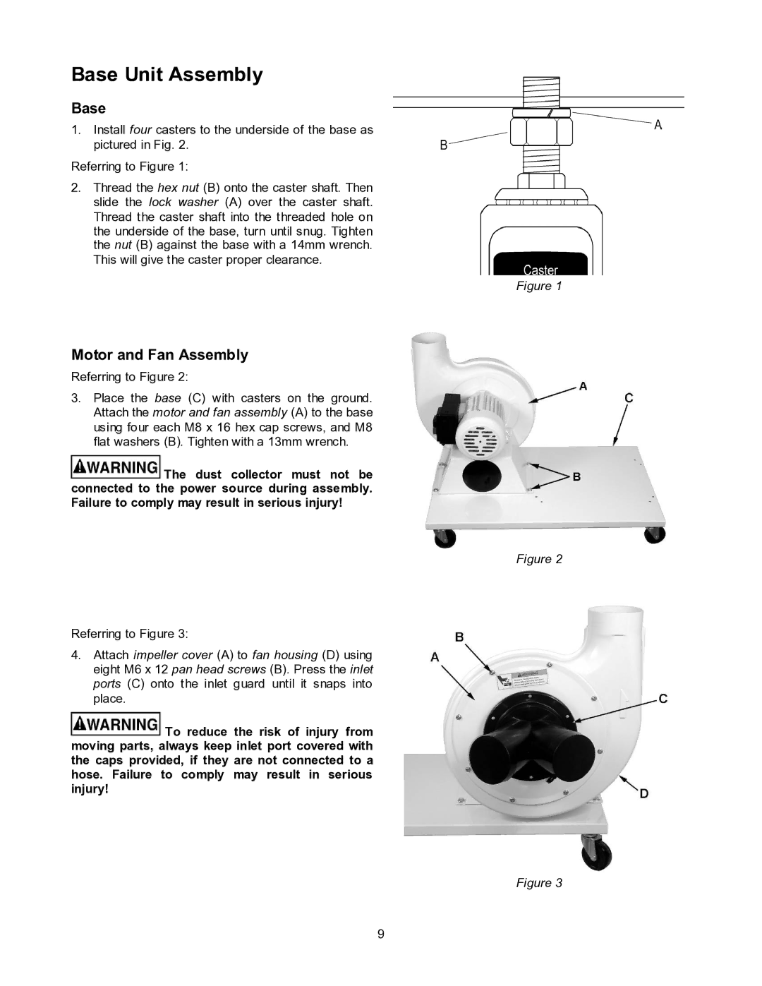
Referring to Figure 1:
2.Thread the hex nut (B) onto the caster shaft. Then slide the lock washer (A) over the caster shaft. Thread the caster shaft into the threaded hole on the underside of the base, turn until snug. Tighten the nut (B) against the base with a 14mm wrench. This will give the caster proper clearance.
Figure 1
Motor and Fan Assembly
Referring to Figure 2:
3.Place the base (C) with casters on the ground. Attach the motor and fan assembly (A) to the base using four each M8 x 16 hex cap screws, and M8 flat washers (B). Tighten with a 13mm wrench.
![]() The dust collector must not be connected to the power source during assembly. Failure to comply may result in serious injury!
The dust collector must not be connected to the power source during assembly. Failure to comply may result in serious injury!
Figure 2
Referring to Figure 3:
4.Attach impeller cover (A) to fan housing (D) using eight M6 x 12 pan head screws (B). Press the inlet ports (C) onto the inlet guard until it snaps into place.
![]() To reduce the risk of injury from moving parts, always keep inlet port covered with the caps provided, if they are not connected to a hose. Failure to comply may result in serious injury!
To reduce the risk of injury from moving parts, always keep inlet port covered with the caps provided, if they are not connected to a hose. Failure to comply may result in serious injury!
Figure 3
9