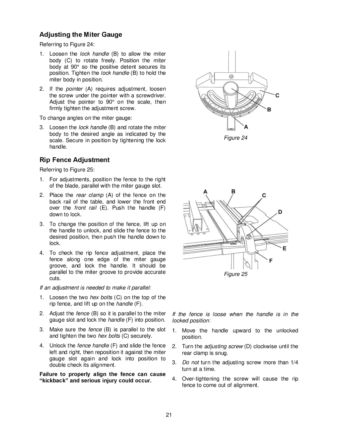
Adjusting the Miter Gauge
Referring to Figure 24:
1.Loosen the lock handle (B) to allow the miter body (C) to rotate freely. Position the miter body at 90° so the positive detent secures its position. Tighten the lock handle (B) to hold the miter body in position.
2.If the pointer (A) requires adjustment, loosen the screw under the pointer with a screwdriver. Adjust the pointer to 90° on the scale, then firmly tighten the adjustment screw.
To change angles on the miter gauge:
3. Loosen the lock handle (B) and rotate the miter body to the desired angle as indicated by the
scale. Secure in position by tightening the lockFigure 24 handle.
Rip Fence Adjustment
Referring to Figure 25:
1.For adjustments, position the fence to the right of the blade, parallel with the miter gauge slot.
2.Place the rear clamp (A) of the fence on the back rail of the table, and lower the front end over the front rail (E). Push the handle (F) down to lock.
3.To change the position of the fence, lift up on the handle to unlock, and slide the fence to the desired position, then push the handle down to lock.
4.To check the rip fence adjustment, place the fence along one edge of the miter gauge groove, and lock the handle. It should be parallel to the miter groove to provide accurate cuts.
If an adjustment is needed to make it parallel:
1.Loosen the two hex bolts (C) on the top of the rip fence, and lift up on the handle (F).
2.Adjust the fence (B) so it is parallel to the miter gauge slot and lock the handle (F) into position.
3.Make sure the fence (B) is parallel to the slot and tighten the two hex bolts (C) securely.
4.Unlock the fence handle (F) and slide the fence left and right, then reposition it against the miter gauge slot again and lock into position to double check its alignment.
Failure to properly align the fence can cause “kickback” and serious injury could occur.
Figure 25
If the fence is loose when the handle is in the locked position:
1.Move the handle upward to the unlocked position.
2.Turn the adjusting screw (D) clockwise until the rear clamp is snug.
3.Do not turn the adjusting screw more than 1/4 turn at a time.
4.
21