Assembly
Note: The letter designators used in the assembly section are the same as those used in the shipping contents and hardware section (page
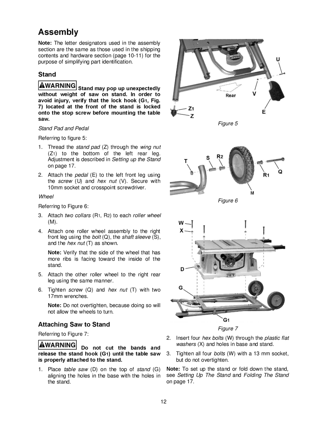
Stand
![]() Stand may pop up unexpectedly without weight of saw on stand. In order to avoid injury, verify that the lock hook (G1, Fig.
Stand may pop up unexpectedly without weight of saw on stand. In order to avoid injury, verify that the lock hook (G1, Fig.
7)located at the front of the stand is locked onto the stop screw before mounting the table saw.
Stand Pad and Pedal
Referring to figure 5:
1.Thread the stand pad (Z) through the wing nut (Z1) to the bottom of the left rear leg. Adjustment is described in Setting up the Stand on page 17.
2.Attach the pedal (E) to the left front leg using the screw (U) and hex nut (V). Secure with 10mm socket and crosspoint screwdriver.
Wheel
Referring to Figure 6:
3.Attach two collars (R1, R2) to each roller wheel
(M).
4.Attach one roller wheel assembly to the right front leg using the bolt (Q), the shaft sleeve (S), and the hex nut (T) as shown.
Note: Verify that the side of the wheel that has more ribs is facing toward the inside of the stand.
5.Attach the other roller wheel to the right rear leg using the same manner.
6.Tighten screw (Q) and hex nut (T) with two 17mm wrenches.
Note: Do not overtighten, because doing so will not allow the wheels to turn.
Attaching Saw to Stand
Referring to Figure 7:
![]() Do not cut the bands and release the stand hook (G1) until the table saw is properly attached to the stand.
Do not cut the bands and release the stand hook (G1) until the table saw is properly attached to the stand.
1.Place table saw (D) on the top of stand (G) aligning the holes in the base with the holes in the stand.
Figure 5
Figure 6
Figure 7
2.Insert four hex bolts (W) through the plastic flat washers (X) and holes in base and stand.
3.Tighten all four bolts (W) with a 13 mm socket, but do not overtighten.
Note: To set up the stand or fold down the stand, see Setting Up The Stand and Folding The Stand on page 17.
12