7.Insert the block labeled “Feed Roller Planing” into the planer opening.
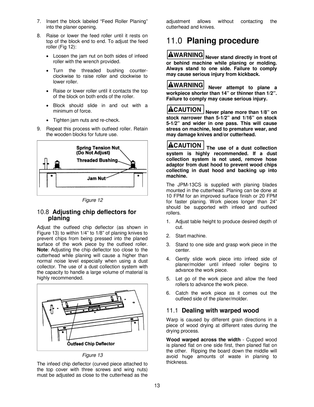
8.Raise or lower the feed roller until it rests on top of the block end to end. To adjust the feed roller (Fig 12):
•Loosen the jam nut on both sides of infeed roller with the wrench provided.
•Turn the threaded bushing counter- clockwise to raise roller and clockwise to lower roller.
•Raise or lower roller until it contacts the top of the block on both ends of the roller.
•Block should slide in and out with a minimum of force.
•Tighten jam nuts and
9.Repeat this process with outfeed roller. Retain the wooden blocks for future use.
Figure 12
10.8Adjusting chip deflectors for planing
Adjust the outfeed chip deflector (as shown in Figure 13) to within 1/4” to 1/8” of planing knives to prevent chips from being pressed into the planed surface of the work piece by the outfeed roller. Note: Adjusting the chip deflector too close to the cutterhead while planing will cause a higher than normal noise level especially when using a dust collector. The use of a dust collection system with the capacity to handle a large volume of material is highly recommended.
Figure 13
The infeed chip deflector (curved piece attached to the top cover with three screws and wing nuts) must be adjusted as close to the cutterhead as the
adjustment allows without contacting the cutterhead and knives.
11.0Planing procedure
![]() Never stand directly in front of or behind machine while planing or molding. Always stand to one side. Failure to comply may cause serious injury from kickback.
Never stand directly in front of or behind machine while planing or molding. Always stand to one side. Failure to comply may cause serious injury from kickback.
![]() Never attempt to plane a workpiece shorter than 14” or thinner than 1/2”. Failure to comply may cause serious injury.
Never attempt to plane a workpiece shorter than 14” or thinner than 1/2”. Failure to comply may cause serious injury.
![]() Never plane more than 1/8” on stock narrower than
Never plane more than 1/8” on stock narrower than
![]() The use of a dust collection system is highly recommended. If a dust collection system is not used, remove hose adaptor from dust hood to prevent wood chips collecting in dust hood and backing up into machine.
The use of a dust collection system is highly recommended. If a dust collection system is not used, remove hose adaptor from dust hood to prevent wood chips collecting in dust hood and backing up into machine.
The
1.Adjust table height to produce desired depth of cut.
2.Start machine.
3.Stand to one side and grasp work piece in the center.
4.Gently slide work piece into infeed side of planer/molder until infeed roller begins to advance the work piece.
5.Let go of the work piece and allow the feed rollers to advance the work piece.
6.Catch the work piece as it comes out the outfeed side of the planer/molder.
11.1Dealing with warped wood
Warp is caused by different grain directions in a piece of wood drying at different rates during the drying process.
Wood warped across the width - Cupped wood is planed flat on one side first, then planed flat on the other. Ripping the board down the middle will avoid huge amounts of waste in planing to thickness.
13