Assembly
![]() Read and understand all assembly instructions before attempting assembly! Failure to comply may cause serious injury!
Read and understand all assembly instructions before attempting assembly! Failure to comply may cause serious injury!
Unpacking and Cleanup
1.Remove all contents from the shipping carton. Keep the saw table upside down (Figure 1) and place on a
2.Inspect the contents for shipping damage. Report damage, if any, to your distributor.
3.Compare the contents of the shipping carton with the contents list in this manual. Report shortages, if any, to your distributor.
Figure 1
Stand Assembly
Refer to Figure 2.
Tool required – 12mm wrench
Mounting Hardware – the stand (excluding wheels) is assembled using 24 each of the following: M8x16 carriage bolts (D), M8 flat washers (E), and M8 hex nuts (F).
The legs consist of one left front leg, one left rear leg and two right legs. The left legs contain the wheel mounting brackets and are not interchange- able. The right legs are interchangeable. Refer to Figure 2 for identification and orientation.
1.Assemble the front left and rear left legs (A, B) to a long top plate (C) using the mounting hardware listed above.
Note: For entire assembly place plates inside legs.
2.Assemble the right legs (G1, G2) to the remaining long top plate (C) in the same manner.
3.Assemble the short top plate with the JET logo
(H)to the front stand legs (A, G1) using the same combination of hardware as used to attach the long top plates.
4.Assemble the remaining short top plate (J) to the rear stand legs (B, G2) in the same manner.
5.Assemble two long support plates (K) to the inside of the left stand legs (A, B) and right stand legs (G1, G2) respectively with the same hardware.
Note: The long support plates have no cutouts.
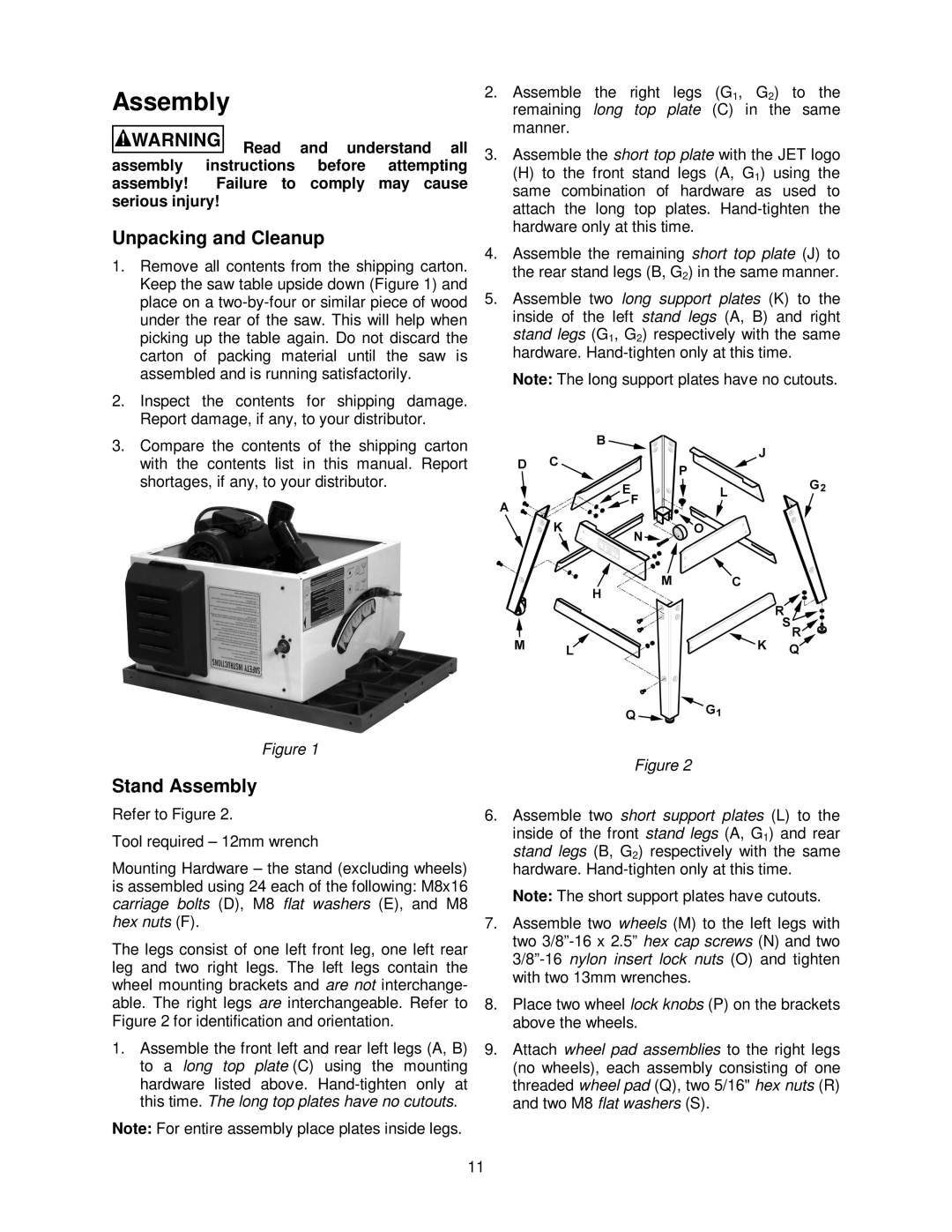
Figure 2
6.Assemble two short support plates (L) to the
inside of the front stand legs (A, G1) and rear stand legs (B, G2) respectively with the same hardware.
Note: The short support plates have cutouts.
7.Assemble two wheels (M) to the left legs with two
8.Place two wheel lock knobs (P) on the brackets above the wheels.
9.Attach wheel pad assemblies to the right legs (no wheels), each assembly consisting of one threaded wheel pad (Q), two 5/16" hex nuts (R) and two M8 flat washers (S).
11