This fence is positioned by lifting up the lock handle (A, Fig. 19) and sliding to the desired location.
Miter Gauge
Operation
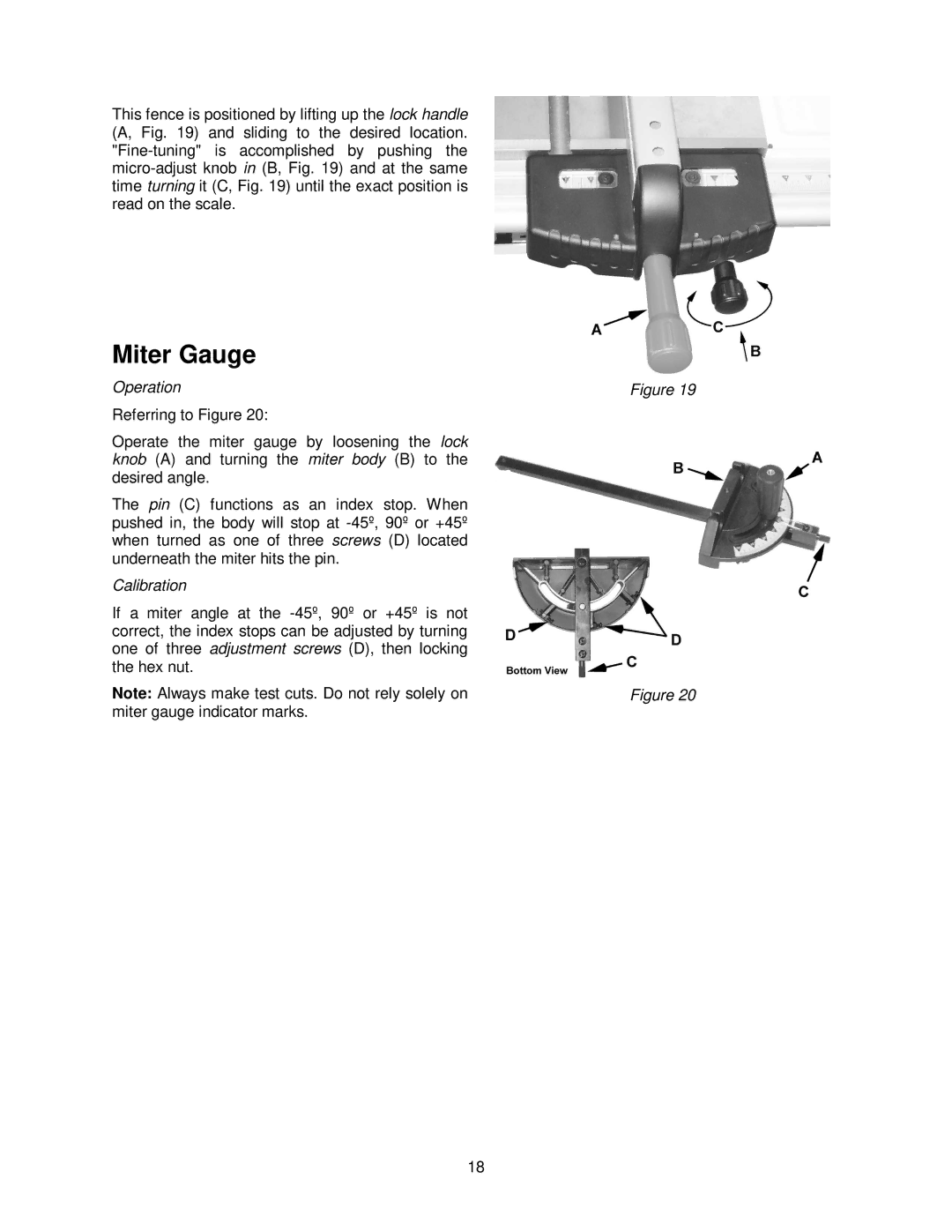
Referring to Figure 20:
Operate the miter gauge by loosening the lock knob (A) and turning the miter body (B) to the desired angle.
The pin (C) functions as an index stop. When pushed in, the body will stop at
Calibration
If a miter angle at the
Note: Always make test cuts. Do not rely solely on miter gauge indicator marks.
18
Figure 19
Figure 20