6 Interface Signal
The
6.1 USB interface
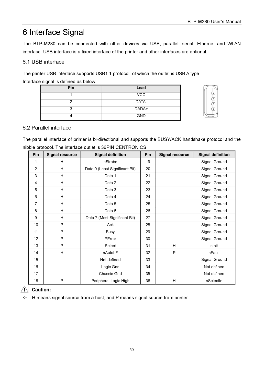
The printer USB interface supports USB1.1 protocol, of which the outlet is USB A type. Interface signal is defined as below:
Pin | Lead |
|
|
1 | VCC |
|
|
2 | DATA- |
|
|
3 | DADA+ |
|
|
4 | GND |
|
|
6.2 Parallel interface
The parallel interface of printer is
Pin | Signal resource | Signal definition | Pin | Signal resource | Signal definition |
1 | H | nStrobe | 19 |
| Signal Ground |
2 | H | Data 0 (Least Significant Bit) | 20 |
| Signal Ground |
3 | H | Data 1 | 21 |
| Signal Ground |
4 | H | Data 2 | 22 |
| Signal Ground |
5 | H | Data 3 | 23 |
| Signal Ground |
6 | H | Data 4 | 24 |
| Signal Ground |
7 | H | Data 5 | 25 |
| Signal Ground |
8 | H | Data 6 | 26 |
| Signal Ground |
9 | H | Data 7 (Most Significant Bit) | 27 |
| Signal Ground |
10 | P | Ack | 28 |
| Signal Ground |
11 | P | Busy | 29 |
| Signal Ground |
12 | P | PError | 30 |
| Signal Ground |
13 | P | Select | 31 | H | nInit |
14 | H | nAutoLF | 32 | P | nFault |
15 |
| Not defined | 33 |
| Signal Ground |
16 |
| Logic Gnd | 34 |
| Not defined |
17 |
| Chassis Gnd | 35 |
| Not defined |
18 | P | Peripheral Logic High | 36 | H | nSelectIn |
Caution:
H means signal source from a host, and P means signal source from printer.
- 30 -
