COMMUNICATION
Programmable Signal Inputs
The UPS incorporates four programmable signal inputs: one
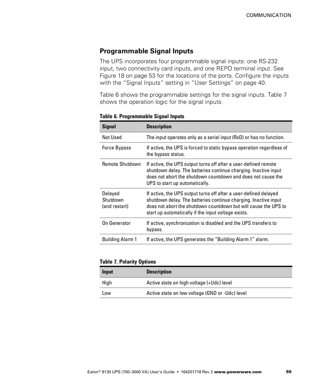
Table 6 shows the programmable settings for the signal inputs. Table 7 shows the operation logic for the signal inputs.
Table 6. Programmable Signal Inputs
Signal | Description |
|
|
Not Used | The input operates only as a serial input (RxD) or has no function. |
|
|
Force Bypass | If active, the UPS is forced to static bypass operation regardless of |
| the bypass status. |
|
|
Remote Shutdown | If active, the UPS output turns off after a |
| shutdown delay. The batteries continue charging. Inactive input |
| does not abort the shutdown countdown and does not cause the |
| UPS to start up automatically. |
|
|
Delayed | If active, the UPS output turns off after a |
Shutdown | shutdown delay. The batteries continue charging. Inactive input |
(and restart) | does not abort the shutdown countdown but will cause the UPS to |
| start up automatically if the input voltage exists. |
|
|
On Generator | If active, synchronization is disabled and the UPS transfers to |
| bypass. |
|
|
Building Alarm 1 | If active, the UPS generates the “Building Alarm 1” alarm. |
|
|
Table 7. Polarity Options
Input | Description |
|
|
High | Active state on high voltage (+Udc) level |
|
|
Low | Active state on low voltage (GND or |
|
|
Eaton® 9130 UPS | 59 |