COMMUNICATION
Relay Output Contacts
The UPS incorporates three programmable relay outputs with potential free contacts for remote alarm indications: a standard relay port and two outputs in the
Configure the relay outputs with the “Relay Configuration” setting in “User Settings” on page 40.
W A R N I N G
The relay output contacts must not be connected to any utility connected circuits. Reinforced insulation to the utility is required. The relay output contacts have a maximum rating of
30 Vac/1A and 60 Vdc/2A nominal values.
Table 5 shows the options for the relay output contacts.
Table 5. Relay Output Configuration Options
Signal | Description |
|
|
UPS ok | Activated when the UPS is feeding the load on inverter or on |
| bypass and no alarms are active |
|
|
On Bypass | Activated when the UPS is NOT on bypass operation |
|
|
On Battery | Activated when the UPS operates on battery and the “On |
| Battery Notice Delay” time has expired |
|
|
Battery Low | Activated with the “Battery Low” alarm according to the |
| “Battery Low Alarm” setting |
|
|
Ext. Charger On | Controls an optional external battery charger on and off |
|
|
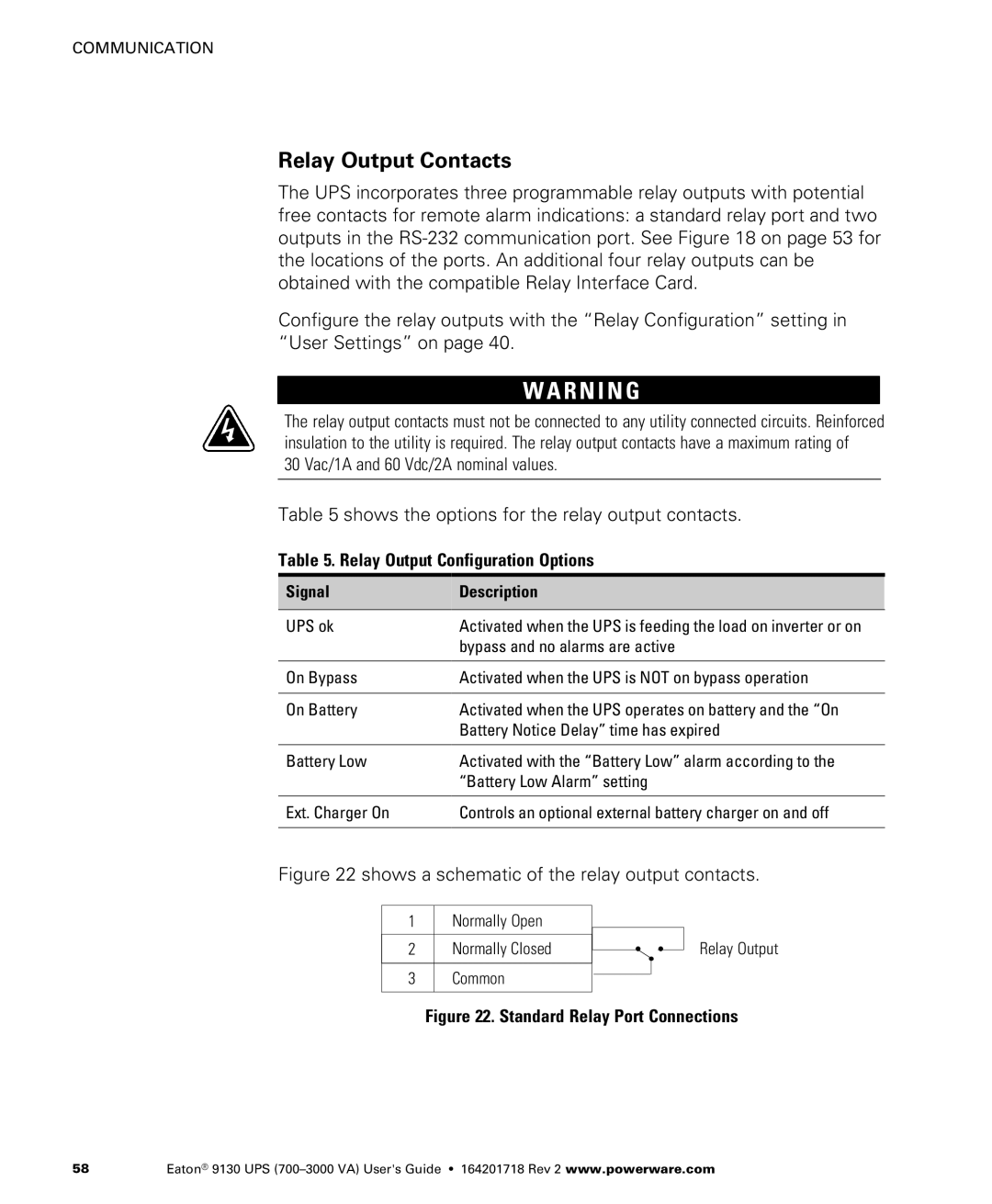
Figure 22 shows a schematic of the relay output contacts.
1Normally Open
2 Normally Closed
3 Common
Relay Output
Figure 22. Standard Relay Port Connections
58 | Eaton® 9130 UPS |